- 2005 Mercedes-Benz M Class Owners Manuals
- Mercedes-Benz M Class Owners Manuals
- 2007 Mercedes-Benz M Class Owners Manuals
- Mercedes-Benz M Class Owners Manuals
- 2003 Mercedes-Benz M Class Owners Manuals
- Mercedes-Benz M Class Owners Manuals
- 2001 Mercedes-Benz M Class Owners Manuals
- Mercedes-Benz M Class Owners Manuals
- 2000 Mercedes-Benz M Class Owners Manuals
- Mercedes-Benz M Class Owners Manuals
- 2009 Mercedes-Benz M Class Owners Manuals
- Mercedes-Benz M Class Owners Manuals
- 2013 Mercedes-Benz M Class Owners Manuals
- Mercedes-Benz M Class Owners Manuals
- 2006 Mercedes-Benz M Class Owners Manuals
- Mercedes-Benz M Class Owners Manuals
- 2012 Mercedes-Benz M Class Owners Manuals
- Mercedes-Benz M Class Owners Manuals
- 2010 Mercedes-Benz M Class Owners Manuals
- Mercedes-Benz M Class Owners Manuals
- 2008 Mercedes-Benz M Class Owners Manuals
- Mercedes-Benz M Class Owners Manuals
- 2011 Mercedes-Benz M Class Owners Manuals
- Mercedes-Benz M Class Owners Manuals
- 2002 Mercedes-Benz M Class Owners Manuals
- Mercedes-Benz M Class Owners Manuals
- 2004 Mercedes-Benz M Class Owners Manuals
- Mercedes-Benz M Class Owners Manuals
- Download PDF Manual
-
may detect the lane markings on the road incorrectly or not at all.
The system may be impaired or may not function if:
lane marking, the system recognizes certain conditions and warns you accordingly.
The warning vibration occurs earlier if:
Ryou approach the outer lane marking on a
Rseveral or no lane markings for a single lane
bend.
are present.
Rthe road has very wide lanes, e.g. a
Rthere is poor visibility, e.g. due to
insufficient illumination of the road, or due to snow, rain, fog or spray.
Rthere is glare, e.g. from oncoming traffic, the sun, or reflection from other vehicles.
Rthe windshield is dirty, fogged up or
covered, for instance by a sticker, in the vicinity of the camera.
Rthe lane markings are worn away, dark or
covered up, e.g. by dirt or snow.
Rthe distance to the vehicle in front is too
small and the lane markings thus cannot be detected.
Rthe lane markings on the road are unclear,
e.g. near roadworks.
Rthe lane markings change quickly, e.g. lanes branch off, cross one another or merge.
Rthe road is narrow and winding.
Active Lane Keeping Assist cannot detect road and traffic conditions. It is not a substitute for attentive driving. You are responsible for the vehicle's speed, braking in good time, and steering correctly. Always adapt your driving style to suit the prevailing road and weather conditions. Always pay attention to traffic conditions and your surroundings. Otherwise, you may fail to recognize dangers in time, cause an accident and injure yourself and others.
Warning vibration in the steering wheel
A warning can be given when a front wheel passes over a lane marking. You will be warned by means of intermittent vibration in the steering wheel for up to 1.5 seconds.
In order that you are warned only when necessary and in good time if you cross the
freeway.
Rthe system recognizes solid lane markings.
The warning vibration occurs later if:
Rthe road has narrow lanes.
Ryou cut the corner on a bend.
Lane-correcting brake application
If you leave your lane under certain circumstances the vehicle will brake briefly on one side. This is meant to assist you in bringing the vehicle back to the original lane.
This function is available in the range between 40 mph and 120 mph (60 km/h to 200 km/h).
A lane-correcting brake application can only be made after driving over a solid, recognizable lane marking. Before this, a warning must be given by means of intermittent vibration in the steering wheel. In addition, a lane with lane markings on both sides must be recognized. The brake application also slightly reduces vehicle speed.
If a lane-correcting brake application occurs, the following, for example, appears in the multifunction display:
i A further lane-correcting brake
application can only occur after your vehicle has returned to the original lane.
G WARNING Active Lane Keeping Assist does not keep your vehicle in its lane. It is only an aid designed to assist driving. It is not a substitute for attentive driving. In some cases, the lane- correcting brake application is not sufficient to bring your vehicle back to the original lane. In such cases, you must steer the vehicle yourself to ensure that it does not leave the lane.
Active Lane Keeping Assist does not detect road and traffic conditions. Always make sure that there is sufficient distance to the side for other traffic or obstacles. In rare cases, unclear markings or particular structures on the roadway can be recognized as solid lane markings. An inappropriate brake application, e.g. after intentionally driving over a solid lane marking, may be interrupted at any time by steering slightly in the opposite direction.
Active Lane Keeping Assist cannot take weather conditions into account.
You are responsible for the driving at appropriate speeds, braking in good time, and steering correctly. Always adapt your driving style to suit the prevailing road and weather conditions. Always pay attention to traffic conditions and your surroundings. Otherwise, you may fail to recognize dangers in time, cause an accident and injure yourself and others.
No lane-correcting brake application occurs if:
Ryou clearly and actively steer, brake or
accelerate.
Ryou cut the corner on a sharp bend.
Ryou switch on the turn signals.
Ra driving safety system intervenes, e.g. ESP®, PRE-SAFE® Brake or Active Blind Spot Assist.
Ryou have adopted a sporty driving style with
high cornering speeds or high rates of acceleration.
Driving systems
207
Ron vehicles with a trailer tow hitch, the
electrical connection to the trailer has been correctly established.
RESP® is switched off.
Rthe transmission is not in position D.
Rthe off-road program is switched on.
Ra loss of tire pressure or a defective tire has
been detected and displayed.
Active Lane Keeping Assist does not detect traffic situations or road users. An inappropriate brake application may be interrupted at any time if you:
Rsteer slightly in the opposite direction.
Ruse a turn signal.
Rclearly brake or accelerate.
A lane-correcting brake application is interrupted automatically if:
Ra driving safety system intervenes, e.g. ESP®, PRE-SAFE® Brake or Active Blind Spot Assist.
Rlane markings can no longer be recognized.
Switching on Active Lane Keeping Assist
X Switch on Active Lane Keeping Assist using
the on-board computer; to do so, select Standard or Adaptive(Y page 233). Symbol : appears in the multifunction display. If Standard is selected, no warning vibration occurs if:
Ryou switch on the turn signals. In this
event, the warnings are suppressed for a certain period of time.
Ra driving safety system intervenes, such
as ABS, BAS or ESP®.
If Adaptive is selected, no warning vibration occurs if:
208 Off-road driving systems
Ryou switch on the turn signals. In this
event, the warnings are suppressed for a certain period of time.
or be fully raised. Observe the instructions for towing the vehicle with all wheels in full contact with the ground.
Ra driving safety system intervenes, e.g.
ABS, BAS or ESP®.
Ryou accelerate hard, e.g. kickdown.
Ryou brake hard.
Ryou steer actively, e.g. swerve to avoid
an obstacle or change lane quickly.
Ryou cut the corner on a sharp bend.
Trailer towing
When you attach a trailer, make sure you have correctly established the electrical connection. This can be accomplished by checking the trailer lighting.
i In wintry driving conditions, the maximum
effect of 4MATIC can only be achieved if you use winter tires (M+S tires), with snow chains if necessary.
! Function or performance tests may only be performed on a 2-axle dynamometer. If you wish to operate the vehicle on such a dynamometer, please consult an authorized Mercedes-Benz Center beforehand. You could otherwise damage the drive train or the brake system.
For information about driving off-road, see (Y page 162).
Off-road driving systems
DSR (Downhill Speed Regulation)
4MATIC (permanent four-wheel drive)
Important safety notes
4MATIC ensures that all four wheels are permanently driven. Together with ESP® and 4ETS, it improves the traction of your vehicle whenever a drive wheel spins due to insufficient grip.
G WARNING If a drive wheel is spinning due to insufficient traction:
RWhile driving off, apply as little throttle as
possible.
RWhile driving, ease up on the accelerator
pedal.
RAdapt your speed and driving style to the
prevailing road conditions.
Failure to observe these guidelines could cause the vehicle to skid.
The 4MATIC cannot prevent accidents resulting from excessive speed.
! Never tow the vehicle with one axle
raised. This may damage the transfer case. Damage of this sort is not covered by the Mercedes-Benz Limited Warranty. All wheels must remain either on the ground
DSR assists you when driving downhill. It keeps the speed of travel at the speed set on the on-board computer. The steeper the downhill gradient, the greater the DSR braking effect on the vehicle. When driving on flat stretches of road or on an uphill gradient, the DSR braking effect is minimal or non- existent.
G WARNING Downhill Speed Regulation (DSR) is a convenience system designed to assist the driver during vehicle operation. The system setting must be appropriate to the topographical and weather conditions encountered, which can change quickly. The driver is responsible for the vehicle speed and for safe brake operation at all times.
Depending on the programmed speed, actual vehicle speed and gradient, switching on DSR while driving can cause the vehicle to slow down rapidly, and you may hear a sound, caused by the activation of the vehicle's brake system through DSR. Sudden and unexpected deceleration can result in loss of vehicle
control, causing an accident and/or serious personal injury to you and others. Do not switch on DSR in a situation where rapid deceleration could result in a loss of vehicle control.
DSR controls the set speed when it is active and the automatic transmission is in the D, R or N position. You can drive at a higher or a lower speed than that set on the on-board computer at any time by accelerating or braking.
G WARNING If you depress the accelerator pedal with DSR activated, the vehicle can drive faster than the programmed set speed. You should therefore drive downhill with particular caution as it could lead to an accident and/or serious injury to you or others. Keep in mind that as soon as you remove your foot from the accelerator pedal with DSR switched on, DSR will start regulating the vehicle's speed including use of brakes if required. Depending on the programmed set speed, actual vehicle speed and gradient, DSR can cause the vehicle to slow down rapidly. Sudden and unexpected deceleration can result in loss of vehicle control, causing an accident and/or serious personal injury to you and others.
For information on driving off-road, see (Y page 162).
Activating/deactivating DSR
Activating
You can only activate DSR if you are driving at 25 mph (40 km/h) or slower.
Off-road driving systems
209
X Press button :.
Indicator lamp ; lights up.
The following messages appear in the multifunction display and in the status indicator, for example:
If the driving speed is too fast, the DSR symbol and the Max. Speed 25 mph (Canada: 40 km/h) message appear in the multifunction display.
i You cannot activate DSR if the SPORT on- road program is activated. The DSR symbol and the Not in Drive Program SPORT message then appear in the multifunction display.
Deactivating X Press button :.
Indicator lamp ; goes out.
The DSR symbol appears in the multifunction display with the Off message.
DSR is deactivated automatically if you are driving faster than 30 mph (Canada: 45 km/h). The DSR symbol appears in the multifunction display with the Off message. Status indicator = goes out. You also hear a warning.
210 Trailer towing
Changing the set speed
When DSR is activated, the set speed can be changed to a value between 1 mph and 10 mph (Canada: between 2 km/h and 18 km/h) during the journey.
Contact a Mercedes-Benz Center if you need further explanation of the information contained in this Operator's Manual.
G WARNING Using a ball coupling other than the one delivered with the vehicle may place too much strain on the trailer tow hitch. This applies especially if the ball coupling in question is longer or angled differently. As a result, the vehicle may be damaged and the trailer may come loose while driving. Handling characteristics may be impaired and the rear axle may be overloaded. This could lead to an accident with serious or even fatal injuries.
Therefore, please observe the following:
X To increase or decrease the set speed
Ronly install the ball coupling delivered with
in 1 mph (Canada: 1 km/h) increments: press the cruise control lever to the point of resistance briefly upwards : for a higher set speed or briefly downwards ; for a lower set speed. The set speed appears in multifunction display ? and is shown in status indicator =.
i The set speed also changes in 1 mph
(Canada: 1 km/h) increments if you press the control lever beyond the point of resistance.
Trailer towing
Notes on towing a trailer
the vehicle.
Rmake sure that the ball coupling is correctly
installed and secured before driving.
Rdo not make any modifications to the ball
coupling or the trailer tow hitch.
G WARNING When backing up the vehicle towards the trailer, make sure there is nobody between the trailer and the vehicle.
Couple and uncouple the trailer carefully. If you do not couple the trailer to the towing vehicle correctly, the trailer could become detached.
Make sure that the following values are not exceeded:
Rthe permissible trailer drawbar noseweight
Important safety notes
Rthe permissible trailer load
G WARNING When towing a trailer, incorrect equipment and driving style could cause you to lose control of the vehicle.
Towing incorrectly or not observing this Operator's Manual could lead to damage to the vehicle and/or serious injuries. Observe the following guidelines to ensure safe trailer towing.
Rthe permissible rear axle load of the towing
vehicle
Rthe maximum permissible gross vehicle
weight of both the towing vehicle and the trailer
You will find the applicable permissible values, which must not be exceeded, in the vehicle documents.
You will find the values approved by the manufacturer on the vehicle identification plates and those for the towing vehicle in the "Technical data" section.
G WARNING When towing a trailer, your vehicle's handling characteristics will be different in comparison with when driving without a trailer.
The vehicle/trailer combination:
Ris heavier
Ris restricted in its acceleration and
gradient-climbing capability
Rhas an increased braking distance
Ris affected more by strong crosswinds
Rdemands more sensitive steering
Rhas a larger turning circle
As a result, the handling characteristics may be impaired and you may lose control of the vehicle. This could lead to an accident with serious or even fatal injuries.
When towing a trailer, always adjust your speed to the current road and weather conditions. Do not exceed the maximum permissible speed for your vehicle/trailer combination.
G WARNING Never depress the brake pedal continuously while the vehicle is in motion, e.g. never cause the brakes to rub by applying constant slight pedal pressure. This causes the brake system to overheat, increases the braking distance and can lead to the brakes failing completely.
G WARNING Under no circumstances try to straighten the vehicle/trailer combination by increasing the speed.
Trailer towing 211
General information
RDo not exceed the legally prescribed
maximum speed for vehicle/trailer combinations in the relevant country.
This lowers the risk of an accident.
ROnly install an approved trailer coupling on
your vehicle.
Further information on availability and on installation is available from any authorized Mercedes-Benz Center.
RThe bumpers of your vehicle are not
suitable for installing detachable trailer couplings.
RDo not install hired trailer couplings or
other detachable trailer couplings on the bumpers of your vehicle.
RTo reduce the risk of damage to the ball
coupling, remove it from the ball coupling recess when not in use.
i When towing a trailer, set the tire
pressure on the rear axle of the towing vehicle for a maximum load; see the tire pressure table in the fuel filler flap (Y page 371).
You will find installation dimensions and loads in the "Technical data" section (Y page 391).
The maximum noseweight of the trailer drawbar on the ball coupling is16. However, the actual noseweight must not exceed the value given on the trailer tow hitch or trailer identification plates. The lowest weight applies.
! Use a drawbar noseweight as close as
possible to the maximum permissible noseweight. Do not use a noseweight of less than the minimum permissible noseweight, as the trailer may otherwise come loose. Missing values were not available at time of going to print.
Note that the payload and the rear axle load are reduced by the actual payload.
16 Missing values unavailable at time of going to print.
212 Trailer towing
Please note that when towing a trailer, PARKTRONIC (Y page 183) and Blind Spot Assist (Y page 198) are only available with limitations, or not at all.
from overheating and wearing too quickly. If you need additional braking, depress the brake pedal repeatedly rather than continuously.
i On vehicles without level control, the
height of the ball coupling will alter according to the load placed on the vehicle. If necessary, use a trailer with a height- adjustable drawbar.
Driving tips
i Observe the information on ESP® trailer
stabilization (Y page 64) and on pulling away with a trailer. (Y page 141).
The maximum permissible speed for vehicle/ trailer combinations depends on the type of trailer. Before beginning the journey, check the trailer's documents to see what the maximum permitted speed is. Observe the legally prescribed maximum speed in the relevant country.
For certain Mercedes-Benz vehicles, the maximum permissible rear axle load is increased when towing a trailer. Refer to the "Technical data" section to find out whether this applies to your vehicle. If you utilize any of the added maximum rear axle load when towing a trailer, the vehicle/trailer combination may not exceed a maximum speed of 60 mph(100 km/h) for reasons concerning the operating permit. This also applies in countries in which the permissible maximum speed for vehicle/trailer combinations is above 60 mph(100 km/h).
When towing a trailer, your vehicle's handling characteristics will be different in comparison with when driving without a trailer.
On long and steep downhill gradients, you must select shift range 1, 2 or 3 in good time.
i This also applies if you have activated
cruise control or DISTRONIC PLUS.
This will use the braking effect of the engine, so that less braking will be required to maintain the speed. This relieves the load on the brake system and prevents the brakes
Driving tips
RMaintain a greater distance from the
vehicle in front than when driving without a trailer.
RAvoid braking abruptly. If possible, brake
gently at first to allow the trailer to run on. Then, increase the braking force rapidly.
RThe values given for gradient-climbing
capabilities from a standstill refer to sea level. When driving in mountainous areas, note that the power output of the engine, and consequently the vehicle's gradient- climbing capability, decrease with increasing altitude.
If the trailer swings from side to side:
X Do not accelerate.
X Do not counter-steer.
X Brake if necessary.
Assembling the ball coupling
! Mercedes-Benz recommends that you
have the ball coupling assembled at a qualified specialist workshop. Only a qualified specialist workshop has the necessary specialist knowledge and tools to carry out the work required. You could otherwise incorrectly assemble the ball coupling or tighten the nut with the incorrect torque. This could lead to the ball coupling and the ball coupling carrier becoming detached while towing a trailer. As a result, you could cause an accident.
Therefore, have the ball coupling assembled at a qualified specialist workshop.
If the assembled ball coupling has been permanently mounted on the vehicle, have the ball coupling regularly checked for
Trailer towing 213
X Insert ball coupling : through the hole in ball coupling carrier ; as far as it will go.
correct installation and torque at a qualified specialist workshop.
G WARNING The ball coupling can be damaged if the nut is tightened on the ball coupling with the incorrect torque. This could cause the trailer to detach while driving and an accident could occur as a result.
Therefore, please observe the following:
Rdo not exceed the maximum permitted
noseweight of the ball coupling, the trailer coupling and the trailer tow hitch.
Rwhen installing, always use a retaining ring between the nut and the mounting surface of the ball coupling carrier.
Rif the assembled ball coupling has been
permanently mounted on the vehicle, have the ball coupling regularly checked for correct installation and torque at a qualified specialist workshop.
Rcheck that the thread under the nut is of
the correct length.
! Mercedes-Benz recommends that you
X Slide retaining ring ? onto the thread of
only use ball couplings tested and approved for use on Mercedes-Benz vehicles. This helps to avoid damage to the vehicle.
Observe the manufacturer's installation instructions if you use a ball coupling other than the one supplied.
i Also observe the height of the trailer coupling and the trailer manufacturer's instructions.
i Depending on the height of the trailer
coupling, it is possible that the ball coupling will have to be rotated by 180° on the ball coupling carrier for correct installation. The assembly is otherwise identical.
ball coupling = as far as it will go.
X Screw on nut A as tightly as possible.
X With a torque wrench, tighten nut B to a
torque of 516 lb-ft (700 Nm).
X Check that projecting thread C has the
requisite length of 0.32 in (8 mm) beneath nut B.
X Check the assembled ball coupling for
correct installation.
214 Trailer towing
Installing the ball coupling
G WARNING If the vehicle/trailer combination is not secured, the trailer may come loose. As a result, you could cause an accident.
Therefore, make sure that the ball coupling is secured with the bolt supplied and the corresponding spring cotter.
G WARNING The ball coupling can be damaged if the nut is tightened on the ball coupling with the incorrect torque. This could cause the trailer to detach while driving and an accident could occur as a result.
Therefore, please observe the following:
Rdo not exceed the maximum permitted
noseweight of the ball coupling, the trailer coupling and the trailer tow hitch.
Rwhen installing, always use a retaining ring between the nut and the mounting surface of the ball coupling carrier.
Rif the assembled ball coupling has been
permanently mounted on the vehicle, have the ball coupling regularly checked for correct installation and torque at a qualified specialist workshop.
Rcheck that the thread under the nut is of
the correct length.
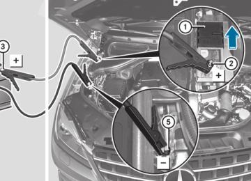
The detachable ball coupling is located in the stowage well under the cargo compartment floor (Y page 292).
X Open the cargo compartment floor
(Y page 292).
Ball coupling and ball coupling stowage well (example)
X Remove ball coupling : with the bolt and
spring cotter from ball coupling stowage well ;.
Protective cap
X Pull protective cap = in the direction of the
arrow, out of the ball coupling recess.
X Place protective cap = into the ball
coupling stowage well.
Ball coupling recess
Trailer towing 215
Correctly installed and secured ball coupling X Check the ball coupling, bolt and spring
cotter for correct installation.
G WARNING If the ball coupling is not correctly installed and secured, the ball coupling and the trailer could come loose. As a result, you could cause an accident.
Therefore, please observe the following:
RMake sure that the ball coupling is secured
with the bolt supplied and the corresponding spring cotter.
RIf the ball coupling cannot be correctly
mounted, remove the ball coupling. Under these circumstances, the ball coupling must not be used for trailer towing.
Have the entire trailer tow hitch checked at a qualified specialist workshop.
Coupling up a trailer
G WARNING Vehicles with air suspension program: While you are coupling or decoupling a trailer, make sure nobody locks or unlocks the vehicle and/ or opens or closes doors or the tailgate.
The vehicle's level could change and you could endanger yourself and/or others as a result.
Make sure that you do not operate the ADS switch or the vehicle level control system when coupling/decoupling the trailer.
Hole in the ball coupling and ball coupling recess
X Insert the ball coupling horizontally into ball coupling recess ? in the direction of the arrow, until the hole in ball coupling A and the hole in ball coupling recess B align.
Bolt
X Slide bolt C all the way into the hole in the ball coupling recess and the ball coupling.
Bolt and spring cotter
X Secure the bolt using spring cotter D.
216 Trailer towing
G WARNING Do not disconnect a trailer with an engaged overrun brake. Otherwise, your hand could become trapped between the bumper and trailer drawbar.
Observe the maximum permissible trailer dimensions (width and length).
Most federal states and all Canadian provinces require by law:
Rsafety chains between the towing vehicle
and the trailer. The chains should be cross- wound under the trailer drawbar. They must be fastened to the vehicle's trailer coupling, not to the bumper or the axle.
Allow for enough play in the chains to facilitate turning tight corners.
Ra separate brake system for certain types
of trailer.
Ra safety switch for braked trailers. Check the specific legal requirements applicable to your federal state.
If the trailer detaches from the towing vehicle, the safety switch applies the trailer's brakes.
! Do not connect the trailer's brake system (if featured) to the hydraulic brake system of the towing vehicle, as the latter is equipped with an anti-lock brake system. Doing so will result in a loss of function of the brake systems of both the vehicle and the trailer.
X Make sure that the automatic transmission
is set to position P.
X Apply the vehicle's electric parking brake.
X Start the engine.
X Vehicles with the AIRMATIC package:
select highway level.
X Vehicles with the adaptive damping system: set ADS to AUTO or COMF.
X Switch off the engine.
X Close all doors and the tailgate.
X Couple up the trailer.
X Establish all electrical connections.
i Vehicles with the AIRMATIC package: if you couple up a trailer, the vehicle always remains at highway level. When coupling up a trailer, please observe the following:
Rif highway level has not been set
manually, the vehicle will automatically sink to highway level as soon as it reaches a speed of 5 mph (8 km/h).
Rhigh-speed level is not available.
These restrictions apply to all accessories powered through a connection to the trailer power socket of your vehicle, e.g. a bicycle carrier.
Towing a trailer
There are numerous legal requirements concerning the towing of a trailer, e.g. speed restrictions. Make sure that your vehicle/ trailer combination complies with the local requirements not only in your area of residence but also at any location to which you are traveling. The police and local authorities can provide reliable information.
Please observe the following when towing a trailer:
RTo acquaint yourself with driving with a trailer and with the resulting changes to handling, you should practice cornering, stopping and backing up in a traffic-free location.
RBefore driving, check:
the trailer tow hitch
the safety switch for braked trailers
the safety chains
the electrical connections
the lights
the wheels
RAdjust the exterior mirrors to provide an
unobstructed view of the rear section of the trailer.
RIf the trailer features electronically
controlled brakes, pull away the vehicle/ trailer combination carefully, manually
Trailer towing 217
brake using the brake controller, and check the brakes for correct function.
blower fan and the interior temperature to maximum.
RSecure any objects on the trailer to prevent the cargo from slipping when the vehicle is in motion.
RWhen overtaking, pay particular attention
to the extended length of your vehicle/ trailer combination.
RIf you couple up a trailer, regularly check the cargo for secure fastening and make sure that the trailer lamps and (if applicable) the trailer brakes are functioning correctly.
RBear in mind that the handling will be less
stable when towing a trailer than when driving without one. Avoid sudden steering movements.
RThe vehicle/trailer combination is heavier, accelerates more slowly, has a decreased gradient climbing capability and a longer braking distance.
It is more susceptible to side winds and requires more careful steering.
RIf possible, avoid abrupt braking. Depress the brake pedal moderately at first, so that the trailer can activate its own brakes. Then increase the pressure on the brake pedal.
RIf the automatic transmission continues to
shift back and forth between two gears when driving up or downhill, restrict the shift range. Select shift range 4, 3, 2, or 1.
A lower gear and lower speed reduce the risk of engine failure.
Due to the length of your vehicle/trailer combination, you will have to travel an additional distance beyond the vehicle you are overtaking before returning to the previous lane.
Decoupling a trailer
G WARNING Vehicles with air suspension program: While you are coupling or decoupling a trailer, make sure nobody locks or unlocks the vehicle and/ or opens or closes doors or the tailgate.
The vehicle's level could change and you could endanger yourself and/or others as a result.
Make sure that you do not operate the ADS switch or the vehicle level control system when coupling/decoupling the trailer.
! Do not disconnect a trailer with an
engaged overrun brake. Otherwise, your vehicle could be damaged by the rebounding of the overrun brake.
X Make sure that the automatic transmission
ROn long and steep gradients that are
is set to position P.
difficult to drive down in shift range 1, switch to the off-road program or engage the LOW GEAR off-road gear.
RWhen driving downhill, shift to a lower gear
to utilize the engine's braking effect.
Avoid continuous brake application as this may overheat the vehicle brakes and, if installed, the trailer brakes.
RIf the coolant temperature increases
dramatically while the air-conditioning system is switched on, switch off the air- conditioning system.
Coolant heat can additionally be dissipated by opening the windows and by setting the
X Apply the vehicle's electric parking brake.
X Start the engine.
X Close all doors and the tailgate.
X Apply the trailer's parking brake.
G WARNING Vehicles with air suspension program: As soon as you disconnect the electrical connection between the trailer and the vehicle, the vehicle will lower. To help avoid personal injury, make sure no one is near the wheel housing or underneath the vehicle before the electrical connection is disconnected.
218 Trailer towing
When you decouple the trailer, the vehicle is temporarily raised because the springs are relieved of load. Be especially careful during this process, as you could otherwise injure yourself and/or others. Make sure that any persons remaining in the vehicle do not press the switches for vehicle level control or the ADS.
X Remove the trailer cable and decouple the
trailer.
X Switch off the engine.
Permissible trailer loads and drawbar
noseweights
Weight specifications
The gross trailer weight is calculated by adding the weight of the trailer to the weight of the load and equipment on the trailer. Maximum gross vehicle weight:17.
The maximum permissible trailer drawbar noseweight is the maximum weight with which the trailer drawbar can be loaded:17
Threshold for Mercedes-Benz approved trailer tow hitches.exceeding the permissible gross axle weight. The permissible gross vehicle weight is indicated on the identification plate on the B-pillar on the driver's side of the vehicle.
i Mercedes-Benz recommends loading the
trailer so that the drawbar noseweight remains between 8% and 15% of the permissible gross trailer weight.
i The weight of additional accessories,
passengers, and cargo reduces the permissible trailer load and drawbar noseweight for your vehicle.
Checking the vehicle and trailer weight
RTo check that the weights of the towing
vehicle and the trailer comply with the maximum permissible values, have the vehicle/trailer combination (including the driver, passengers, and cargo with a fully laden trailer) weighed on a calibrated weighbridge.
RCheck the gross axle weight rating of the
front and rear axles, the gross weight of the trailer and trailer drawbar noseweight.
Loading a trailer
Removing the ball coupling
RWhen loading the trailer, make sure that
X Remove the spring cotter.
neither the permissible gross weight of the trailer nor the gross vehicle weight are exceeded. The permissible gross vehicle weight is indicated on the identification plate on the B-pillar on the driver's side of the vehicle.
You can find the maximum permissible values on the type plates of your vehicle and the trailer. Always observe the lowest respective value when determining the maximum weight with which you can load the vehicle and the trailer.
RThe trailer drawbar load on the ball coupling must be added to the rear axle load to avoid
X Remove the bolt from the ball coupling
recess.
X Remove the ball coupling from the ball
coupling recess.
X Clean the ball coupling if it is dirty.
Information on cleaning and care of the trailer tow hitch can be found at (Y page 322).
Storing the ball coupling
G WARNING Do not carry the ball coupling in the vehicle interior if it is not secured.
17 Missing values were not available at time of going to print.
Otherwise, you and others could be injured by the ball coupling being thrown around if you:
Rbrake sharply
Rchange direction suddenly
Rare involved in an accident
X Open the stowage well under the cargo
compartment floor.
X Remove the protective cap from the ball
coupling recess.
X Press the protective cap into the ball
coupling recess until it engages.
X Make sure that the protective cap is firmly
in place.
X Store the ball coupling in the ball coupling
recess with the bolt and spring cotter inserted.
Trailer power supply
The trailer socket of your vehicle is equipped at the factory with a permanent power supply.
The permanent power supply is supplied via trailer socket pin 4.
! You can connect accessories with a
maximum power consumption of 240 W to the permanent power supply.
You must not charge a trailer battery using the power supply.
The trailer's permanent power supply is switched off in the event of low vehicle supply voltage and after six hours at the latest.
You can obtain further information about installing the trailer electrics from a qualified specialist workshop, e.g. an authorized Mercedes-Benz Center.
Trailer towing 219
220
Useful information ............................ 222
Important safety notes .................... 222
Displays and operation .................... 222
Menus and submenus ...................... 226
Display messages ............................. 238
Warning and indicator lamps in the instrument cluster ............................ 269
221
222 Displays and operation
Useful information
Rmalfunction/warning messages
i This Operator's Manual describes all models and all standard and optional equipment of your vehicle available at the time of publication of the Operator's Manual. Country-specific differences are possible. Please note that your vehicle may not be equipped with all features described. This also applies to safety- related systems and functions.
i Please read the information on qualified
specialist workshops (Y page 25).
Important safety notes
You will find an illustration of the instrument cluster in the "At a glance" section (Y page 29).
G WARNING A driver's attention to the road and traffic conditions must always be his/her primary focus when driving.
For your safety and the safety of others, selecting features through the multifunction steering wheel should only be done by the driver when traffic and road conditions permit it to be done safely.
Bear in mind that at a speed of just 30 mph (approximately 50 km/h ), your vehicle is covering a distance of 44 feet (approximately 14 m) every second.
G WARNING No messages will be displayed if either the instrument cluster or the multifunction display is inoperative.
As a result, you will not be able to see information about your driving conditions, such as
Rspeed
Routside temperature
Rwarning/indicator lamps
Rfailure of any systems
Driving characteristics may be impaired.
If you must continue to drive, do so with added caution. Contact an authorized Mercedes- Benz Center as soon as possible.
G WARNING Malfunction and warning messages are only indicated for certain systems and are intentionally not very detailed. The malfunction and warning messages are simply a reminder with respect to the operation of certain systems. They do not replace the owner's and/or driver's responsibility to maintain the vehicle's operating safety. Have all required maintenance and safety checks performed on the vehicle. Bring the vehicle to an authorized Mercedes-Benz Center to address the malfunction and warning messages.
Displays and operation
Coolant temperature display
G WARNING Driving when your engine is overheated can cause some fluids which may have leaked into the engine compartment to catch fire. You could be seriously burned.
Steam from an overheated engine can cause serious burns which can occur just by opening the engine hood. Stay away from the engine if you see or hear steam coming from it.
Stop the vehicle in a safe location away from other traffic. Turn off the engine, get out of the vehicle and do not stand near the vehicle until the engine has cooled down.
The coolant temperature gauge is in the instrument cluster on the right-hand side.
Under normal operating conditions and with the specified coolant level, the coolant temperature may rise to 248 ‡ (120 †).
Displays and operation 223
! If the coolant temperature is too high a
display message is shown.
The segments between the speed of the vehicle in front and the stored speed light up.
If the coolant temperature rises above 248 ‡(120 †), do not drive any further as this could damage the engine.
Tachometer
The red band in the tachometer indicates the engine's overrevving range.
! Do not drive in the overrevving range, as
this could damage the engine.
The fuel supply is interrupted to protect the engine when the red band is reached.
Outside temperature display
The outside temperature display is in the multifunction display (Y page 224).
G WARNING The outside temperature indicator is not designed to serve as an ice-warning device and is therefore unsuitable for that purpose.
Indicated temperatures just above the freezing point do not guarantee that the road surface is free of ice. The road may still be icy, especially in wooded areas or on bridges.
Changes in the outside temperature are displayed after a short delay.
Speedometer with segments
The segments in the speedometer indicate which speed range is available.
Cruise control (Y page 167) activated:
The segments light up from the stored speed to the maximum speed.
DISTRONIC PLUS (Y page 169) activated:
One or two segments in the set speed range light up.
DISTRONIC PLUS detects a vehicle in front:
Operating the on-board computer
Overview
The on-board computer is activated as soon as you turn the SmartKey to position 1 in the ignition lock.
You can control the multifunction display and the settings in the on-board computer using the buttons on the multifunction steering wheel.
: Multifunction display
; To switch on the Voice Control System; see the separate operating instructions
= Right control panel
? Left control panel
A Back button
224 Displays and operation
Left control panel
RCalls up the menu and menu bar
Press briefly:
RScrolls through lists
RSelects a submenu or function RIn the Audio menu: selects a
stored station, an audio track or a video scene
RIn the Tel (telephone) menu:
switches to the phone book and selects a name or telephone number
Press and hold:
RIn the Audio menu: selects the previous/next station or selects an audio track or a video scene using rapid scrolling
RIn the Tel (telephone) menu:
starts rapid scrolling through the phone book
a RConfirms a selection/display
message
RIn the Tel (telephone) menu:
switches to the telephone book and starts dialing the selected number
RIn the Audio menu: stops the station search function at the desired station
Right control panel
~ RRejects or ends a call
RExits phone book/redial
memory
6 RMakes or accepts a call
RSwitches to the redial memory
RAdjusts the volume
8 RMute
Back button
% Press briefly:
RBack
RSwitches off the Voice Control
System
RHides display messages or calls up the last Trip menu function used
RExits the telephone book/redial
memory
% Press and hold:
RCalls up the standard display in
the Trip menu
Multifunction display
Values and settings as well as display messages are shown in the multifunction display.
: Time
; Outside temperature or speed
(Y page 234)
= Description field
? Menu bar
A Transmission position
For further information on displaying the transmission position, see (Y page 145).
The following messages may appear in the multifunction display:
XjY
Active Parking Assist (Y page 186)
CRUISE Cruise control (Y page 167) ÃDSR DSR (Y page 208) è Rear window wiper (Y page 118) À ATTENTION ASSIST (Y page 194) Ã Lane Keeping Assist (Y page 200)
or Active Lane Keeping Assist (Y page 205)
HOLD function (Y page 179)
HOLD Ä PRE-SAFE® Brake (Y page 65)
Displays and operation 225
226 Menus and submenus
Menus and submenus
Menu overview
The number of menus shown depends on the optional equipment in the vehicle.
Function
Trip menu (Y page 227)
Navi menu (navigation instructions) (Y page 228)
Audio menu (Y page 229)
Tel menu (telephone) (Y page 230)
DriveAssist menu (assistance) (Y page 232)
Service menu (Y page 233)
Rcalls up display messages (Y page 238)
Rtire pressure loss warning system (Canada only) (Y page 357)
Rtire pressure monitor (Y page 359)
RASSYST PLUS service interval display (Y page 317)
Sett. menu (Y page 233)
Trip menu
Standard display
X Press and hold the % button on the
steering wheel until the Trip menu with odometer : and trip odometer ; is shown.
Trip computer "From start" or "From
reset"
The values in the From Start submenu are calculated from the start of a journey, while the values in the From Reset submenu are calculated from the last time the submenu was reset (Y page 228). X Press the = or ; button on the
steering wheel to select the Trip menu. X Press the 9 or : button to select
From Start or From Reset.
Trip computer "From start" (example) : Distance
; Time
= Average speed
? Average fuel consumption
The From Start trip computer is reset automatically if:
Rthe ignition has been switched off for more
than four hours.
R999 hours have been exceeded.
R9,999 miles have been exceeded.
Menus and submenus
227
When 9,999 hours or 99,999 miles have been exceeded, the trip computer is automatically reset From Reset.
Displaying the range and current fuel
consumption
X Press the = or ; button on the
steering wheel to select the Trip menu. X Press the 9 or : button to select
current fuel consumption and approximate range.
: Approximate range
; Current fuel consumption
Approximate range : is calculated according to current driving style and the amount of fuel in the tank. If there is only a small amount of fuel left in the fuel tank, the display shows a vehicle being refueled C instead of range :.
Digital speedometer
X Press the = or ; button on the
steering wheel to select the Trip menu. X Press 9 or : to select the digital
speedometer.
: Digital speedometer
228 Menus and submenus
Resetting values
Route guidance inactive
You can reset the values of the following functions:
RTrip odometer
RTrip computer "From start"
RTrip computer "From reset" X Press the = or ; button on the
steering wheel to select the Trip menu.
: Direction of travel
X Press the9 or: button to select the
; Current road
function that you wish to reset.
X Press a.
Route guidance active
No change of direction announced
Resetting the trip computer "From start" (example)
X Press : to select Yes and press a
: Distance to the destination
to confirm.
; Distance to the next change of direction
Navigation system menu
Displaying navigation instructions
In the Navi menu, the multifunction display shows navigation instructions. For more information, see the separate operating instructions.
X Switch on COMAND (see the separate
operating instructions).
X Press the = or ; button on the
steering wheel to select the Navi menu.
= Current road
? Symbol for "follow the road's course"
Change of direction announced without a
lane recommendation
: Road into which the change of direction
leads
; Distance to change of direction and visual
distance display
= Symbol for change of direction
When ach ange of direction has been announced, you will see visual distance display ; next to the symbol for the change of direction =. This decreases in size as you approach the announced change of direction.
Menus and submenus
229
Change of direction announced with a
ROff Map or Off Mapped Road: the vehicle
lane recommendation
Lane recommendations are only displayed if