- 2005 Mercedes-Benz M Class Owners Manuals
- Mercedes-Benz M Class Owners Manuals
- 2007 Mercedes-Benz M Class Owners Manuals
- Mercedes-Benz M Class Owners Manuals
- 2003 Mercedes-Benz M Class Owners Manuals
- Mercedes-Benz M Class Owners Manuals
- 2001 Mercedes-Benz M Class Owners Manuals
- Mercedes-Benz M Class Owners Manuals
- 2000 Mercedes-Benz M Class Owners Manuals
- Mercedes-Benz M Class Owners Manuals
- 2009 Mercedes-Benz M Class Owners Manuals
- Mercedes-Benz M Class Owners Manuals
- 2013 Mercedes-Benz M Class Owners Manuals
- Mercedes-Benz M Class Owners Manuals
- 2006 Mercedes-Benz M Class Owners Manuals
- Mercedes-Benz M Class Owners Manuals
- 2012 Mercedes-Benz M Class Owners Manuals
- Mercedes-Benz M Class Owners Manuals
- 2010 Mercedes-Benz M Class Owners Manuals
- Mercedes-Benz M Class Owners Manuals
- 2008 Mercedes-Benz M Class Owners Manuals
- Mercedes-Benz M Class Owners Manuals
- 2011 Mercedes-Benz M Class Owners Manuals
- Mercedes-Benz M Class Owners Manuals
- 2002 Mercedes-Benz M Class Owners Manuals
- Mercedes-Benz M Class Owners Manuals
- 2004 Mercedes-Benz M Class Owners Manuals
- Mercedes-Benz M Class Owners Manuals
- Download PDF Manual
-
You can unlock and open the tailgate simultaneously from the outside when the vehicle is at a standstill. 왘 Press and hold button Š on the
SmartKey or SmartKey with KEYLESS-GO* until the tailgate unlocks and opens. While the tailgate is opening, an acoustic signal sounds.
or 왘 Vehicles with KEYLESS-GO*:
Pull on the handle (컄 page 120). The tailgate is unlocked and opens. While the tailgate is opening, an acous- tic signal sounds.
Opening the tailgate from the inside You can unlock and open the tailgate si- multaneously from the driver’s seat when the vehicle is at a standstill.
Warning!
Maintain sight of the area around the rear of the vehicle while operating the tailgate with the door-mounted remote tailgate switch or with the Š button on the SmartKey or SmartKey with KEYLESS-GO*. Monitor the opening procedure carefully to make sure no one is in danger of being injured.
To interrupt the opening procedure, press or pull the door-mounted remote tailgate switch or press the Š button on the SmartKey or SmartKey with KEYLESS-GO*.
121
Controls in detail Locking and unlocking
The switch is located in the driver’s door.
1 Remote tailgate switch 왘 Pull remote tailgate switch 1 until
tailgate begins to open. The tailgate opens. While the tailgate is opening, an acoustic signal sounds.
122
Limiting opening height of tailgate* In vehicles with power tailgate*, the tail- gate opening height can be limited when transporting goods on a roof rack* (e.g. presence of an MB roof cargo container*). When activated, the tailgate opens to approximately 6.6 ft (2.00 m). 왘 Activate the limiting opening height of
tailgate using the control system (컄 page 176).
Closing the tailgate from the inside You can close the tailgate from the inside using the remote tailgate switch. If the tailgate comes into contact with an object while closing (e.g. luggage that has been piled too high) the closing procedure is stopped and the tailgate reopens.
Warning!
Maintain sight of the area around the rear of the vehicle while operating the tailgate with the door-mounted switch. Monitor the closing procedure carefully to make sure no one is in danger of being injured.
To interrupt the closing procedure, press or pull the door-mounted remote tailgate switch or press the Š button on the SmartKey or SmartKey with KEYLESS-GO*.
Even with the SmartKey or the SmartKey with KEYLESS-GO* removed from the starter switch or the SmartKey with KEYLESS-GO* removed from the vehicle, the remote tailgate switch can be operated. Therefore, do not leave children unattended in the vehicle, or with access to an unlocked vehicle. A child’s unsupervised access to a vehicle could result in an accident and/or serious personal injury.
왘 Press remote tailgate switch 1
(컄 page 122) until tailgate begins to close. The tailgate closes. While the tailgate is closing an acoustic signal sounds.
To interrupt the closing procedure: 왘 Press or pull remote tailgate switch 1
(컄 page 122).
Closing the tailgate from the outside You can close the tailgate from the outside using the tailgate closing switch or the Š button on the SmartKey or SmartKey with KEYLESS-GO*. In vehicles with KEYLESS-GO*, you can also simulta- neously lock the vehicle. If the tailgate comes into contact with an object while closing (e.g. luggage that has been piled too high) the closing procedure is stopped and the tailgate reopens.
Vehicles without KEYLESS-GO* 1 Tailgate closing switch
Controls in detail Locking and unlocking
Vehicles with KEYLESS-GO* 1 Tailgate closing switch 왘 Press tailgate closing switch 1 or the
Š button on the SmartKey or SmartKey with KEYLESS-GO* briefly. The tailgate closes and an acoustic warning sounds.
Warning!
Monitor the closing procedure carefully to make sure no one is in danger of being in- jured. To prevent possible personal injury, 컄컄
123
Controls in detail Locking and unlocking
컄컄
always keep hands and fingers away from the cargo compartment opening when clos- ing the tailgate. Be especially careful when small children are around. To stop the clos- ing procedure, do one of the following: 앫 Press tailgate closing switch 1
(컄 page 123).
앫 Press KEYLESS-GO* locking/closing
switch* 1 (vehicles with KEYLESS-GO*) (컄 page 124).
앫 Press the Š button on the SmartKey
(컄 page 110) or SmartKey with KEYLESS-GO* (컄 page 113).
앫 Press or pull the remote tailgate switch
on the driver’s door (컄 page 122).
Even with the SmartKey removed from the starter switch or the SmartKey with KEYLESS-GO* removed from the vehicle, the tailgate closing switch can be operated. Therefore, do not leave children unattended in the vehicle, or with access to an unlocked vehicle. A child’s unsupervised access to a vehicle could result in an accident and/or serious personal injury.
124
i Do not place the SmartKey or SmartKey with KEYLESS-GO* in the open cargo compartment. You may lock yourself out.
i If the vehicle was previously centrally locked, the tailgate will lock automatically after closing it. The turn signals will flash three times to confirm locking.
Closing the tailgate and locking the vehicle from the outside (vehicles with KEYLESS-GO*) In vehicles with power tailgate and KEYLESS-GO*, you can close the tailgate and lock the vehicle simultaneously from the outside using the KEYLESS-GO* locking/closing switch. If the tailgate comes into contact with an object while closing (e.g. luggage that has been piled too high), the closing procedure is stopped and the tailgate reopens. 왘 Make sure you have the SmartKey with
KEYLESS-GO* with you.
1 KEYLESS-GO* locking/closing switch 왘 Press KEYLESS-GO* locking/closing
switch 1 briefly. The tailgate closes automatically. Once the tailgate is closed, the vehicle locks if doors are closed. The turn signals flash three times to confirm locking. The locking knobs in the doors move down. The anti-theft alarm system is armed.
Even with the SmartKey with KEYLESS-GO* removed from the vehicle, the tailgate closing switch can be operated. Therefore, do not leave children unattended in the vehi- cle, or with access to an unlocked vehicle. A child’s unsupervised access to a vehicle could result in an accident and/or serious personal injury.
i To prevent a possible inadvertent lockout, the tailgate will open automatically if a SmartKey with KEYLESS-GO* is recognized inside the vehicle.
Warning!
Monitor the closing procedure carefully to make sure no one is in danger of being in- jured. To prevent possible personal injury, always keep hands and fingers away from the cargo compartment opening when clos- ing the tailgate. Be especially careful when small children are around. To stop the clos- ing procedure, do one of the following: 앫 Press tailgate closing switch 1
(컄 page 123).
앫 Press KEYLESS-GO* locking/closing
switch* 1 (컄 page 124).
앫 Press the Š button on the SmartKey
with KEYLESS-GO* (컄 page 113).
앫 Press or pull the remote tailgate switch
on the driver’s door (컄 page 122).
Controls in detail Locking and unlocking
Automatic central locking
The doors and the tailgate lock automati- cally when the ignition is switched on and the wheels are turning at vehicle speeds of approximately 9 mph (15 km/h) or more.
i You can open a locked door from the inside. Open door only when conditions are safe to do so.
i The doors unlock automatically after an accident if the force of the impact exceeds a preset threshold. The vehicle automatically locks when the ignition is switched on and the wheels are turning at vehicle speeds of approximately 9 mph (15 km/h) or more. You could therefore lock yourself out when the vehicle 앫 is pushed or towed 앫 is on a test stand For information on towing the vehicle, see “Towing the vehicle” (컄 page 499). You can deactivate the automatic central locking mode using the control system (컄 page 175).
125
Controls in detail Locking and unlocking
Locking and unlocking from the inside
You can lock or unlock the doors and the tailgate from inside using the central lock- ing or unlocking switch. This can be useful, for example, if you want to lock the vehicle before starting to drive. The fuel filler flap cannot be locked or un- locked with the central locking or unlock- ing switch.
Warning!
When leaving the vehicle, always remove the SmartKey or SmartKey with KEYLESS-GO* from the starter switch, take it with you, and lock the vehicle. Do not leave children unat- tended in the vehicle, or with access to an unlocked vehicle. A child’s unsupervised access to a vehicle could result in an accident and/or serious personal injury.
126
The switches are located in the drivers door.
1 Central unlocking switch 2 Central locking switch
Locking 왘 Press central locking switch 2.
If all doors and the tailgate are closed, the vehicle locks.
Unlocking 왘 Press central unlocking switch 1.
The vehicle unlocks.
i You can open a locked door from inside at any time. Open door only when conditions are safe to do so. If the vehicle was previously centrally locked with the SmartKey or with KEYLESS-GO*, it will not unlock using the central unlocking switch. If the vehicle was previously locked with the central locking switch: 앫 and the SmartKey or SmartKey with
KEYLESS-GO* is set to factory settings, the complete vehicle is unlocked when a front door is opened from the inside
앫 and the SmartKey or SmartKey with
KEYLESS-GO* is set to selective settings, only the front door opened from the inside is unlocked
i With the passenger-side door opened, you cannot lock the vehicle with the central locking switch.
You cannot remove the active head restraints on the driver’s and front passenger’s seat. For removal of the active head restraints we recommend that you contact an authorized Mercedes-Benz Light Truck Center. For information on head restraint adjust- ment, see “Seats” (컄 page 43). For information on active head restraints, see “Active head restraint” (컄 page 88).
왔 Seats For information on seat adjustment, see the “Getting started” section (컄 page 43). For more information on seats, see “Load- ing” (컄 page 266).
Front seat active head restraints
Warning!
For your protection, drive only with properly positioned head restraints.
Adjust the head restraint so that it is close to the head as possible and the center of the head restraint supports the back of the head at eye level. This will reduce the potential for injury to the head and neck in the event of an accident or similar situation.
Controls in detail Seats
Rear seat head restraints
Warning!
Do not drive the vehicle without the seat head restraints installed when the rear seats are occupied. Head restraints are intended to help reduce injuries during an accident.
With a rear seat occupied, make sure to move the respective head restraint up from the lowest non-use position and have the oc- cupant adjust the head restraint properly.
For your protection, drive only with properly positioned head restraints.
Adjust the head restraint in such a way that it is as close to the head as possible and the center of the head restraint supports the back of the head at eye level. This will re- duce the potential for injury to the head and neck in the event of an accident or similar situation.
127
Controls in detail Seats
Head restraint height
Head restraint fore and aft adjustment
Head restraints, removing and install- ing
1 Head restraint 2 Release button Raising: 왘 Manually adjust the height of head
restraint 1 by pulling it upward to the desired position.
Lowering: 왘 To lower head restraint 1, press
release button 2 and push down on head restraint 1.
Manually adjust the angle of the head restraint. 왘 While seated, reach behind you with
both hands and find lower edge of the head restraint.
왘 Adjust the head restraint to the desired
position by pushing or pulling on the lower edge of the head restraint cush- ion.
1 Head restraint 2 Release button
Removing 왘 Pull head restraint 1 to its uppermost
position.
왘 Press release button 2 and pull out
head restraint.
128
Controls in detail Seats
Installing 왘 Insert head restraint 1 into openings
on the seat backrest.
왘 Push head restraint 1 down until it au-
dibly engages.
왘 Press release button 2 and adjust
head restraint 1 to the desired posi- tion (컄 page 128).
For more information on seats, see the “Getting started” section (컄 page 43).
Lumbar support
Multicontour seat*
The curvature of the driver’s seat can be adjusted to help enhance lower back sup- port and seating comfort. The lever for lumbar support adjustment is located on the right hand side of the driver’s seat backrest.
The multicontour seat has an extendable seat cushion and inflatable air chambers built into the backrest to provide additional lumbar and side support. The seat cushion depth, seat backrest cushion-height and curvature can be con- tinuously varied with switches on the in- side of each front seat base after the ignition is switched on (컄 page 39).
1 Adjustment lever 왘 Move adjustment lever 1 in direction
of arrows until you have reached a comfortable seating position.
1 Seat cushion depth 2 Backrest side bolsters 3 Backrest center 4 Backrest bottom
129
Controls in detail Seats
왘 Switch on the ignition (컄 page 40).
Seat heating*
The switches for front-seat heating are lo- cated in the center console.
The switches for rear seat heating are located in the rear center console.
1 Seat heating switch, front seats 2 Indicator lamps
1 Seat heating switch, rear seats 2 Indicator lamps
Seat cushion depth 왘 Adjust the seat cushion depth to the
length of your upper leg with switch 1.
Backrest contour 왘 Adjust the contour of the seat backrest
to the desired position with switch æ or ç.
왘 Move the backrest support to the bot-
tom with button 4 or to the center with button 3.
Backrest side bolsters 왘 Adjust the side bolsters so that they
provide good lateral support using switch 2.
130
Controls in detail Seats
왘 Switch on the ignition (컄 page 40).
Seat ventilation*
The switches for the seat ventilation are located in the center console.
1 Seat ventilation switch, front seats 2 Indicator lamps
Switching on 왘 Press switch 1.
Three red indicator lamps 2 in the switch come on.
왘 Continue pressing switch 1 until
desired seat heating level is reached.
Switching off 왘 Press switch 1 repeatedly until all
indicator lamps 2 go out.
i If one or more of the indicator lamps 2 on seat heating switch 1 (컄 page 130) are flash- ing, there is insufficient voltage available since too many electrical consumers are switched on. The seat heating switches off automatically. The seat heating will switch back on again automatically as soon as sufficient voltage is available.
The red indicator lamps in the switch come on to show which heating level you have selected.
Level
off
Three indicator lamps on (highest level) The seat heating automatically switches to level 2 after approx- imately 5 minutes. Two indicator lamps on The seat heating automatically switches to level 1 after approx- imately 10 minutes. One indicator lamp on (lowest level) The seat heating automatically switches off after approximately 20 minutes. No indicator lamp on
131
Controls in detail Seats
The blue indicator lamps in the switch come on to show which ventilation level you have selected.
Switching on 왘 Press button 1 repeatedly until the
desired ventilation level is set.
Level
off
Three indicator lamps on (highest level) Two indicator lamps on One indicator lamp on (lowest level) No indicator lamp on
왘 Switch on the ignition (컄 page 40).
i The seat ventilation for the driver’s seat is automatically set to the highest level if activated via summer opening feature (컄 page 237).
Switching off 왘 Press button 1 repeatedly until all
indicator lamps 2 go out.
132
왔 Memory function* Prior to operating the vehicle, the driver should check and adjust the seat height, seat position fore and aft, and seat back- rest angle if necessary, to ensure adequate control, reach and comfort. The head restraint should also be adjusted for proper height. See also the section on air bags (컄 page 74) for proper seat posi- tioning. In addition, adjust the steering wheel to ensure adequate control, reach, operation and comfort. Both the interior and exterior rear view mirrors should be adjusted for adequate rear vision. Fasten seat belts. Infants and small chil- dren should be seated in a properly se- cured restraint system that complies with U.S. Federal Motor Vehicle Safety Stan- dards 213 and 225 and Canadian Motor Vehicle Safety Standards 213 and 210.2.
With the memory function you can store up to three different configurations. Each stored position on the driver’s side includes the following settings: 앫 Seat position 앫 Multicontour seat*: previously saved
setting
앫 Steering wheel position 앫 Exterior rear view mirrors’ position Each stored position on the passenger side includes the following settings: 앫 Seat position 앫 Multicontour seat*: previously saved
setting
Warning!
Do not activate the memory function while driving. Activating the memory function while driving could cause the driver to lose control of the vehicle.
Controls in detail Memory function*
The memory button and stored position buttons are located on the entry side of each front seat base.
1, 2, 3
Memory button Stored position buttons
133
Controls in detail Memory function*
Storing positions into memory
Recalling positions from memory
왘 Adjust the seats (컄 page 43). 왘 On the driver’s side, additionally adjust the steering wheel (컄 page 48) and ex- terior rear view mirrors (컄 page 49) to the desired positions.
왘 Press memory button M. 왘 Release memory button M and press stored position button 1, 2 or 3 within 3 seconds. All settings are stored to the selected position.
! Do not operate the power seats using memory button M if the seat backrest is in an excessively reclined position. Doing so could cause damage to front or rear seats. Move seat backrest to an upright position first. 왘 Press and hold stored position
button 1, 2 or 3 until the seat, steering wheel and exterior rear view mirrors have fully moved to the stored posi- tions.
i Releasing the stored position button stops movement to the stored positions immediately.
134
왔 Lighting For information on how to switch on the headlamps and use the turn signals, see “Switching on headlamps” (컄 page 59) and “Turn signals” (컄 page 60).
i If you drive in countries where vehicles drive on the other side of the road than the country in which the vehicle is registered, you must have the headlamps modified for symmetrical low beams. Relevant information can be obtained at any authorized Mercedes-Benz Light Truck Center.
i Vehicles equipped with active Bi-Xenon* headlamps: The active Bi-Xenon* headlamps monitor the vehicles steering angle and vehicle speed, then automatically shift their beams to either side to better follow the curvature of the road ahead, increasing usable illumination over conventional headlamps.
Exterior lamp switch
1 ‚ Standing lamps, left (turn left two
stops)
2 ˆ Standing lamps, right (turn left
one stop)
3 M Off
Daytime running lamp mode (컄 page 137)
4 U Automatic headlamp mode
Daytime running lamp mode (컄 page 137)
Controls in detail Lighting
5 C Parking lamps (also side marker lamps, tail lamps, license plate lamps, instrument panel lamps) 6 B Low beam headlamps or high
beam headlamps 7 ‡ Front fog lamps 8 † Rear fog lamp
i The exterior lamps switch off automatically when you remove the SmartKey from the starter switch or open the driver’s door with the ignition switched off. When the parking lamps or the rear fog lamp are switched on and you remove the SmartKey from the starter switch or open the driver’s door, an acoustic signal sounds. In addition the message Switch Off Lights appears in the multifunction display. Switch off the parking lamps or the rear fog lamp manually.
! Failure to switch off the parking lamps when leaving the vehicle may result in a discharged battery.
135
Controls in detail Lighting
Low beam headlamps 왘 Turn the exterior lamp switch to
position B. With the SmartKey in starter switch position 1 or the KEYLESS-GO* start/stop button pressed once, the following lamps will switch on: 앫 Tail and parking lamps 앫 License plate lamps 앫 Side marker lamps With the SmartKey in starter switch position 2 or the KEYLESS-GO* start/stop button pressed twice, the following lamps will switch on addition- ally: 앫 Low beam headlamps 앫 High beam headlamps (when the combination switch is pushed for- ward)
136
Automatic headlamp mode The following lamps switch on and off au- tomatically depending on the brightness of the ambient light: 앫 Low beam headlamps 앫 Tail and parking lamps 앫 License plate lamps 앫 Side marker lamps
Warning!
If the exterior lamp switch is set to U, the headlamps will not be automatically switched on under foggy conditions.
To minimize risk to you and to others, activate headlamps by turning exterior lamp switch to B when driving or when traffic and/or ambient lighting conditions require you to do so.
In low ambient lighting conditions, only switch from position U to B with the vehicle at a standstill in a safe location. Switching from U to B will briefly switch off the headlamps. Doing so while driving in low ambient lighting conditions may result in an accident.
The automatic headlamp feature is only an aid to the driver. The driver is responsible for the operation of the vehicle’s lights at all times.
왘 Turn the exterior lamp switch to
position U. With the SmartKey in starter switch position 1 or the KEYLESS-GO* start/stop button pressed once, only the parking lamps and the side marker lamps will switch on and off depending on the brightness of the ambient light. When the engine is running, the low beam headlamps, the tail and parking lamps, the license plate lamps, and the side marker lamps will switch on and off depending on the brightness of the ambient light.
i Canada only: High beam headlamps are only available with the exterior lamp switch in position B.
Controls in detail Lighting
Daytime running lamp mode In Canada the daytime running lamp mode is mandatory and therefore in a constant mode. In the USA the daytime running lamp mode is deactivated by default. Activate the day- time running lamp mode using the control system, see “Setting daytime running lamp mode (USA only)” (컄 page 170). 왘 Turn the exterior lamp switch to
position M or U. When the engine is running, the low beam headlamps are switched on. In low ambient light conditions, the following lamps will switch on additionally: 앫 Tail and parking lamps 앫 License plate lamps 앫 Side marker lamps
i With the daytime running lamp mode activated and the engine running, you cannot switch off the low beam headlamps manually.
Canada only
i With the exterior lamp switch in position M or U, you cannot switch on the high beam headlamps. The high beam flasher is available at all times. For nighttime driving turn the exterior lamp switch to position B to permit activation of the high beam headlamps.
When the engine is running, and you shift from a driving position to position N or P with the vehicle at a standstill, the low beam headlamps will switch off with a three-minute delay. When the engine is running, and you 앫 turn the exterior lamp switch to
position C, the low beam head- lamps, the tail and parking lamps, the side marker lamps and the license plate lamps switch on
앫 turn the exterior lamp switch to
position B, the manual headlamp mode has priority over the daytime running lamp mode
137
Controls in detail Lighting
USA only
i With the exterior lamp switch in position M, you cannot switch on the high beam headlamps. The high beam flasher is available at all times. For nighttime driving turn the exterior lamp switch to position B or U to permit activation of the high beam headlamps.
When the engine is running, and you turn the exterior lamp switch to position C or B, the manual headlamp mode has priority over the daytime running lamp mode. The corresponding exterior lamps switch on (컄 page 135).
138
Locator lighting and night security illumination The locator lighting and the night security illumination are described in the “Control system” section, see “Setting locator light- ing” (컄 page 171) and “Setting night secu- rity illumination” (컄 page 171).
Fog lamps
Warning!
In low ambient lighting or foggy conditions, only switch from position U to B with the vehicle at a standstill in a safe location. Switching from U to B will briefly switch off the headlamps. Doing so while driving in low ambient lighting conditions may result in an accident.
i Fog lamps will operate with the parking lamps and/or the low beam headlamps on. Fog lamps should only be used in conjunction with low beam headlamps. Consult your State or Province Motor Vehicle Regulations regarding permissible lamp operation.
i Fog lamps cannot be switched on with the exterior lamp switch in position U. To switch on the fog lamps, turn the exterior lamp switch to position B first.
Front fog lamps 왘 Turn the exterior lamp switch to
position C or B (컄 page 135).
Rear fog lamp (driver’s side only) 왘 Turn the exterior lamp switch to
position B (컄 page 135).
왘 Pull out the exterior lamp switch to first
왘 Pull out the exterior lamp switch to
Combination switch
Controls in detail Lighting
stop. The front fog lamps switch on. The green indicator lamp ‡ in the exterior lamp switch comes on. 왘 Push in the exterior lamp switch.
The front fog lamps switch off. The green indicator lamp ‡ in the exterior lamp switch goes out.
second stop. The rear fog lamp switches on. The yellow indicator lamp † in the exterior lamp switch comes on.
왘 Push in the exterior lamp switch to first
stop. The rear fog lamp switches off. The yellow indicator lamp † in the exterior lamp switch goes out. The front fog lamps remain lit.
1 High beam 2 High beam flasher
High beam 왘 Turn the exterior lamp switch to
position B (컄 page 135).
왘 Push the combination switch in
direction of arrow 1 to switch on the high beam. The high beam headlamp indicator lamp A in the instrument cluster comes on (컄 page 26).
컄컄
139
Controls in detail Lighting
컄컄
왘 Pull the combination switch in direction
Corner-illuminating front fog lamps*
Driving forward
of arrow 2 to its original position to switch off the high beam. The high beam headlamp indicator lamp A in the instrument cluster goes out.
High beam flasher 왘 Pull the combination switch briefly in
direction of arrow 2.
The corner-illuminating front fog lamps im- prove illumination of the area in the direc- tion into which you are turning. The corner-illuminating front fog lamps will operate with the engine running and with 앫 the exterior lamp switch in position B (컄 page 135) or
앫 the exterior lamp switch in position U (컄 page 135) or
앫 the daytime running lamp mode
activated (컄 page 137)
i The corner-illuminating front fog lamps will only come on in low ambient lighting conditions.
i If you are driving faster than 25 mph (40 km/h) or have the front fog lamps switched on, the corner-illuminating function is not avail- able.
Switching on corner-illuminating front fog lamps 왘 Switch on the left or right turn signal (컄 page 60), depending on whether you are turning left or right. The respective front fog lamp comes on and illuminates the area in the direc- tion into which you are turning.
or 왘 Turn steering wheel in desired direc-
tion. The front fog lamp on the side of your steering direction comes on.
i The corner-illuminating front fog lamps temporarily come on on both sides of the vehicle if you turn the steering wheel in one direction and then again in the other direction shortly thereafter.
140
i The corner-illuminating front fog lamps will come on automatically depending on the steer- ing angle and vehicle speed, even if you did not switch on either turn signal. If the corner-illuminating front fog lamps came on automatically, they will also go out automatically depending on the steering angle and vehicle speed.
Switching off corner-illuminating front fog lamps The combination switch for the turn signal resets automatically after major steering wheel movements. This will switch off the corner-illuminating front fog lamps if they were activated by switching on the left or right turn signal. If the turn signal should stay on after making the turn, the turn signal and the corner-illuminating front fog lamps can be switched off by returning the combination switch to its original position.
i There may be a brief delay before the corner-illuminating front fog lamps switch off.
Controls in detail Lighting
Driving in reverse
Hazard warning flasher
The hazard warning flasher can be switched on at all times, even with the SmartKey removed from the starter switch or with the SmartKey with KEYLESS-GO* removed from the vehicle. The hazard warning flasher switches on automatically when an air bag deploys. The hazard warning flasher switch is located on the center console.
Switching on corner-illuminating front fog lamps 왘 Shift the automatic transmission to
reverse gear R (컄 page 185). The front fog lamp opposite to your steering direction comes on.
Switching off corner-illuminating front fog lamps 왘 Shift the automatic transmission to a
gear other than reverse gear R (컄 page 185). The respective corner-illuminating front fog lamp goes out.
1 Hazard warning flasher switch
141
Controls in detail Lighting
Switching on hazard warning flasher 왘 Press hazard warning flasher
switch 1. All turn signals are flashing.
i With the hazard warning flasher activated and the combination switch set for either left or right turn, only the respective turn signals will operate when the ignition is switched on.
Switching off hazard warning flasher 왘 Press hazard warning flasher switch 1
again.
i If the hazard warning flasher has been activated automatically, press hazard warning flasher switch 1 once to switch it off.
Interior lighting
The controls for interior lighting are locat- ed in the overhead control panel.
142
! An interior lamp switched on manually does not go out automatically. Leaving an interior lamp switch in the ON position for extended periods of time with the engine turned off could result in a discharged battery.
Automatic control
i The interior lighting is factory-set to automatic mode.
Deactivating 왘 Press switch 3.
The switch engages in the recessed position. The interior lighting and the locator lighting (컄 page 171) remain switched off even when you 앫 unlock the vehicle 앫 open a door 앫 open the tailgate 앫 remove the SmartKey from the
starter switch
1 Front left reading lamp switch 2 Rear interior lighting switch 3 Automatic control switch 4 Front interior lighting switch 5 Front right reading lamp switch 6 Front right interior lamp 7 Front right reading lamp 8 Front left reading lamp 9 Front left interior lamp
Activating 왘 Press switch 3.
The switch disengages from its recessed position back to its original position. The interior lighting and the locator lighting (컄 page 171) come on when you 앫 unlock the vehicle 앫 open a door 앫 open the tailgate 앫 remove the SmartKey from the
starter switch
The interior lamps go out following an adjustable time delay (컄 page 172).
i If a door remains open, the interior lamps switch off automatically after approximately 5 minutes when the SmartKey is removed or in starter switch position 0.
Manual control
i An interior lamp switched on manually does not go out automatically.
Switching front/rear interior lighting on and off 왘 Press front/rear interior lighting switch 4 or 2 to switch on the respective interior light.
왘 Press front/rear interior lighting
switch 4 or 2 again to switch off the respective interior light.
Switching front reading lamps on and off 왘 Press front reading lamp switch 1
or 5 to switch on the respective front reading lamp.
왘 Press front reading lamp switch 1
or 5 again to switch off the respective front reading lamp.
Controls in detail Lighting
Switching rear interior reading lamps on and off The rear interior reading lamps are located above the side windows.
Passenger side reading lamp 1 Rear interior reading lamp 왘 Press on reading lamp 1 where indi-
cated by arrow. The reading lamp comes on.
왘 Press on reading lamp 1 once more.
The reading lamp goes out.
143
Controls in detail Lighting
Door entry lamps
Cargo compartment lamp
For better orientation in the dark, the corresponding door entry lamps comes on when you open a door and the automatic control is activated. The door entry lamps will switch off when the corresponding door is closed.
The cargo compartment lamp comes on when the tailgate is opened. If you leave the tailgate open for an extend- ed period of time, the cargo compartment lamp will switch off automatically after ap- proximately 5 minutes.
i If you turn the SmartKey in the starter switch to position 0 or remove the SmartKey from the starter switch, the door entry lamps will remain lit for approximately 5 minutes.
144
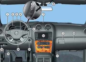
왔 Instrument cluster For a full view illustration of the instrument cluster, see “Instrument cluster” (컄 page 26).
1 To dim instrument cluster illumination 2 Reset button 3 To brighten instrument cluster
illumination
The instrument cluster is activated when you 앫 open a door 앫 switch on the ignition (컄 page 40) 앫 press reset button 2
앫 switch on the exterior lamps(컄 page 135)
i Opening a front door or pressing the reset button without switching on the ignition or the exterior lighting activates the multifunction display illumination only for 30 seconds.
For information on changing the instru- ment cluster settings, e.g. the language, see “Instrument cluster submenu” (컄 page 167).
Warning!
No messages will be displayed if either the instrument cluster or the multifunction display is inoperative.
As a result, you will not be able to see infor- mation about your driving conditions, such as speed or outside temperature, warn- ing/indicator lamps, malfunction/warning messages or the failure of any systems. Driving characteristics may be impaired.
If you must continue to drive, do so with added caution. Contact an authorized Mercedes-Benz Light Truck Center as soon as possible.
Controls in detail Instrument cluster
Adjusting instrument cluster illumina- tion
Use button 1 or 3 to adjust the illumina- tion brightness for the instrument cluster.
i The instrument cluster illumination is dimmed or brightened automatically to suit am- bient light conditions. The instrument cluster illumination will also be adjusted automatically when you switch on the vehicle’s exterior lamps.
i With the exterior lighting switched on, the brightness of the switches in the center console will also be adjusted when using button 1 or 3.
To brighten illumination 왘 Press and hold button 3 until the
desired level of illumination is reached.
To dim illumination 왘 Press and hold button 1 until the
desired level of illumination is reached.
145
Controls in detail Instrument cluster
Resetting trip odometer
Make sure you are viewing the trip odome- ter display (컄 page 147). 왘 If it is not displayed, press button è or ÿ on the multifunction steering wheel (컄 page 148) repeatedly until the trip odometer appears in the multi- function display.
왘 Press and hold reset button 2 in the instrument cluster (컄 page 145) until the trip odometer is reset.
Tachometer
The red marking on the tachometer (컄 page 26) denotes excessive engine speed.
! Avoid driving at excessive engine speeds, as it may result in serious engine damage that is not covered by the Mercedes-Benz Limited Warranty.
146
To help protect the engine, the fuel supply is interrupted if the engine is operated within the red marking.
Outside temperature indicator
Warning!
The outside temperature indicator is not de- signed to serve as an ice-warning device and is therefore unsuitable for that purpose.
Indicated temperatures just above the freez- ing point do not guarantee that the road sur- face is free of ice. The road may still be icy, especially in wooded areas or on bridges.
The outside temperature is displayed in the multifunction display (컄 page 147).
The temperature sensor is located in the front bumper area. Due to its location, the sensor can be affected by road or engine heat during idling or slow driving. This means that the accuracy of the displayed temperature can only be verified by com- parison to a thermometer placed next to the sensor, not by comparison to external displays (e.g. bank signs etc.). When moving the vehicle into colder ambi- ent temperatures (e.g. when leaving your garage), you will notice a delay before the lower temperature is displayed. A delay also occurs when ambient temper- atures rise. This prevents inaccurate tem- perature indications caused by heat radiated from the engine during idling or slow driving.
왔 Control system The control system is activated as soon as the SmartKey in the starter switch is turned to position 1 (컄 page 40) or as soon as the KEYLESS-GO start/stop but- ton* is in position 1 (컄 page 42). The con- trol system enables you to 앫 call up information about your vehicle 앫 change vehicle settings For example, you can use the control sys- tem to find out when your vehicle is next due for maintenance service, to set the language for messages in the instrument cluster display, and much more.
Controls in detail Control system
Warning!
Multifunction display
A driver’s attention to the road and traffic conditions must always be his/her primary focus when driving.
For your safety and the safety of others, se- lecting features through the multifunction steering wheel should only be done by the driver when traffic and road conditions per- mit it to be done safely.
Bear in mind that at a speed of just 30 mph (approximately 50 km/h), your vehicle is covering a distance of 44 feet (approximate- ly 14 m) every second.
The control system relays information to the multifunction display.
1 Trip odometer 2 Main odometer 3 Transmission position indicator 4 Current transmission program mode1
5 Status indicator (outside temperatureor digital speedometer)
For more information on menus displayed in the multifunction display, see “Menus” (컄 page 150).
1 AMG vehicles only.
147
Controls in detail Control system
Multifunction steering wheel
The displays in the multifunction display and the settings in the control system are controlled by the buttons on the multifunc- tion steering wheel.
148
1 Multifunction display
Operating the control system
6 0 Voice Control System* off1, see separate operating instructions
2 Telephone*: Press button s to take a call
to dial to redial
t to end a call
to reject an incoming call 3 Selecting the submenu or setting
the volume: Press button æ up/to increase ç down/to decrease
4 ! Voice Control System* on1, see separate operating instructions
5 Moving within a menu:
Press button j for next display k for previous display
1 Vehicles without Voice Control System*: Button
without function.
7 Menu systems:
Press button è for next menu ÿ for previous menu
Depending on the selected menu (컄 page 150), pressing the buttons on the multifunction steering wheel will alter what is shown in the multifunction display. The information available in the multifunc- tion display is arranged in menus, each containing a number of functions or sub- menus. The individual functions are then found within the relevant menu (radio or CD operations under AUDIO, for example). These functions serve to call up relevant information or to customize the settings for your vehicle.
Controls in detail Control system
The menus are described on the following pages.
It is helpful to think of the menus, and the functions within each menu, as being ar- ranged in a circular pattern. 앫 If you press button è or ÿ
repeatedly, you will pass through each menu one after the other.
앫 If you press button k or j
repeatedly, you will pass through each function display, one after the other, in the current menu.
In the Settings menu, instead of functions, you will find a number of submenus for calling up and changing settings. For instructions on using these submenus, see “Settings menu” (컄 page 163). The number of menus available in the sys- tem depends on which optional equipment is installed in your vehicle.
149
Controls in detail Control system
Menus
This is what you will see when you scroll through the menus 1 to 6.
The table on the next page provides an overview of the individual menus.
150
Controls in detail Control system
Menu 5
NAV* (컄 page 161) Route guidance in- structions, current direction traveledMenu 6
AIRMATIC*/Compass (컄 page 162) CompassVehicle level*
Menus, submenus and functions
Menu 1
Standard display (컄 page 154) Trip- and main odometer Engine oil tem-Menu 2
AMG1
(컄 page 156)perature
Vehicle supply voltage RACETIMER
Overall analysis
Lap analysis
Checking tire inflation pressure Checking coolant tem- perature Calling up digital speed- ometer or outside tem- perature Calling up maintenance service indicator
1 AMG vehicles only.
Menu 4
Menu 3
Off-road Mode1 AUDIO (컄 page 159) Off-road driving program on/off(컄 page 160) Selecting radio station
Selecting satellite radio station* Operating CD player
i The headings used in the menus table are designed to facilitate navigation within the
system and are not necessarily identical to those shown in the control system displays. The first
function displayed in each menu will automati- cally show you which part of the system you are in.
151
Controls in detail Control system
This is what you will see when you scroll through the menus 7 to b.
The table on the next page provides an overview of the individual menus.
152
Controls in detail Control system
Menus, submenus and functions
Menu 7
Vehicle status message memory1
(컄 page 162) Calling up malfunction messages, warning mes- sages, and system status messages stored in mem- oryMenu 8
SettingsMenu 9
Vehicle configurationMenu a Trip computer
Menu b TEL*
(컄 page 163) Resetting to factory settings
(컄 page 177) DSR (Downhill Speed Reg- ulation) programmed default speed
(컄 page 178) Fuel consumption statistics since start
(컄 page 180) Loading phone book
Instrument cluster submenu Time/Date submenu
Lighting submenu Vehicle submenu Comfort submenu*
Searching for name in phone book
Fuel consumption sta- tistics since last reset Resetting fuel consump- tion statistics Distance to empty
1 The vehicle status message memory menu is only displayed if there is a message stored.
i The headings used in the menus table are designed to facilitate navigation within the
system and are not necessarily identical to those shown in the control system displays. The first
function displayed in each menu will automati- cally show you which part of the system you are in.
153
Controls in detail Control system
Standard display menu
The following functions are available:
Checking coolant temperature
In the standard display, the main odometer and the trip odometer appear in the multi- function display.
Function Page Checking tire inflation pressure 359
154
Checking coolant temperature Calling up digital speedometer 155
or outside temperature Calling up maintenance service indicator388
1 Trip odometer 2 Main odometer 왘 If you see another display, press
button è or ÿ repeatedly until the standard display appears.
왘 Press button k or j to select the functions in the standard display menu.
154
Warning!
앫 Driving when your engine is overheated can cause some fluids which may have leaked into the engine compartment to catch fire. You could be seriously burned.
앫 Steam from an overheated engine can cause serious burns which can occur just by opening the hood. Stay away from the engine if you see or hear steam coming from it.
Stop the vehicle in a safe location away from other traffic. Turn off the engine, get out of the vehicle and do not stand near the vehicle until the engine has cooled down.
Controls in detail Control system
왘 Press button k or j repeatedly until the coolant temperature appears in the multifunction display.
Calling up digital speedometer or outside temperature 왘 Press button k or j repeatedly
until the digital speedometer or the outside temperature appears in the multifunction display.
i You can select whether the digital speedom- eter or the outside temperature is shown in the multifunction display. You can change the setting in the submenu Instrument Cluster via the function Status Line Display, see “Selecting display (digital speedometer or outside temperature) for status indicator” (컄 page 168).
! Excessive coolant temperature triggers a warning message in the multifunction display (컄 page 431). The engine should not be operated with the coolant temperature above 248°F (120°C). Doing so may cause serious engine damage which is not covered by the Mercedes-Benz Limited Warranty.
i During severe operating conditions, e.g. stop-and-go traffic, the coolant temperature may rise close to 248°F (120°C).
Digital speedometer
Outside temperature
155
Use buttons k or j to select the following functions in the AMG menu:
Function Vehicle supply voltage RACETIMER Overall analysis Lap analysis
Page 156
157
158
159i If the engine reaches the overspeed range in the manual shift program (컄 page 195), the menu will be shown in red. In addition, you will see UP next to gear indicator 1 as a reminder to upshift.
Vehicle supply voltage 왘 Press button è or ÿ repeatedly
until the AMG menu appears in the multifunction display.
왘 Press button j repeatedly until the vehicle supply voltage appears in the multifunction display.
1 Gear indicator 2 Vehicle supply voltage
Controls in detail Control system
AMG menu
i This function is only available in AMG vehicles.
The main screen of the AMG menu shows you the gear currently engaged as well as the engine oil temperature. 왘 Press button è or ÿ repeatedly
until the AMG menu appears in the multifunction display.
1 Gear indicator 2 Engine oil temperature
i The engine oil temperature value flashes if the engine oil temperature has not yet reached 80°C. During this time, avoid driving at full engine speed.
156
RACETIMER
Warning!
왘 Press button j repeatedly until the RACETIMER appears in the multifunc- tion display.
Starting the RACETIMER 왘 Press button æ.
The timer starts.
Controls in detail Control system
The RACETIMER feature is only for use on roads and in conditions where high speed driving is permitted. Racing on public roads is prohibited under all circumstances and the driver is and must always remain re- sponsible for following posted speed limits.
The RACETIMER allows you to time and save driving stretches in hours, minutes and seconds. 왘 Press button è or ÿ repeatedly
until the AMG menu appears in the multifunction display.
1 Gear indicator 2 RACETIMER 3 Lap number
i You can start the RACETIMER when the engine is running or the starter switch is in position 2 (컄 page 40).
i While the RACETIMER is being displayed, you cannot adjust the audio volume using buttons æ or ç.
Displaying intermediate time 왘 Press button ç while the timer is
running. The intermediate time is shown for 5 seconds.
Stopping the RACETIMER 왘 Press button æ.
The timer stops.
i When you stop the vehicle and turn the SmartKey to position 1 (컄 page 40) or, in vehi- cles with KEYLESS-GO*, turn off the engine and do not open the driver’s door, the RACETIMER stops timing. Timing is resumed when you switch the ignition back on (컄 page 40) or restart the engine (컄 page 54) and then press button æ.
157
Controls in detail Control system
Saving lap time and starting a new lap
i You can save up to nine laps. 왘 Press button ç while the timer is
running. The intermediate time will be shown for 5 seconds.
왘 Press button ç within 5 seconds. The intermediate time shown will be saved as a lap time. The RACETIMER begins timing the new lap. The new lap begins to be timed as soon as the intermediate time is called up.
1 Gear indicator 2 RACETIMER 3 Best lap time 4 Lap number
158
Resetting current lap 왘 Press button æ while the timer is
running. The timer stops.
왘 Press button ç.
The lap time is reset to “0”.
Deleting all laps
i It is not possible to delete a single saved lap. 왘 Press button æ while the timer is
running. The timer stops.
왘 Press the reset button twice
(컄 page 26).
왘 Press button æ.
The timer starts. The saved laps are deleted.
i When you switch off the engine, the RACETIMER will be reset to“0” after 30 seconds. All laps are deleted.
Overall analysis
i These functions are only available if you have saved at least one lap and have stopped the RACETIMER. 왘 Press button è or ÿ repeatedly until the AMG menu appears in the mul- tifunction display.
왘 Press button j repeatedly until the
overall analysis appears in the multi- function display.
1 Overall analysis of RACETIMER 2 Overall driving time 3 Maximum speed 4 Overall distance driven 5 Average speed
Lap analysis
i These functions are only available if you have saved at least two laps and have stopped the RACETIMER. 왘 Press button è or ÿ repeatedly until the AMG menu appears in the mul- tifunction display.
왘 Press button j repeatedly until the
lap analysis appears in the multifunc- tion display.
Controls in detail Control system
i Each lap is shown in its own submenu. The fastest lap is indicated by flashing symbol 1.
The symbol y appears in the lower multifunction display.
Off-road Mode menu
i This function is only available in AMG vehicles.
Use this function to switch the off-road driving program (컄 page 253) On or Off. 왘 Press button è or ÿ repeatedly until the Off-road mode menu appears in the multifunction display.
i The setting is stored when you turn off the engine.
1 Lap number 2 Lap time 3 Maximum speed 4 Lap length 5 Average speed during lap 왘 Press button j or k to see
other lap analyses.
Off-road mode 왘 Press button æ or ç to switch the off-road driving program On or Off.
159
Controls in detail Control system
AUDIO menu
The functions in the AUDIO menu operate the audio equipment which you currently have turned on. If no audio equipment is currently turned on, the message AUDIO Off appears in the multifunction display. The following functions are available:
Page Function Selecting radio station 160
Selecting satellite radio station* 160
Operating CD player 161Selecting radio station 왘 Turn on the COMAND system and
select radio. Refer to separate COMAND system operating instruc- tions.
왘 Press button è or ÿ repeatedly
until the currently tuned station appears in the multifunction display.
160
1 Waveband setting 2 Station frequency 왘 Press button k or j repeatedly
until the desired station is found. The station search depends on the se- lected setting in the Vehicle submenu of the control system (컄 page 175). Pressing button k or j will either start a frequency scan or select the next stored radio station.
i You can only store new stations using the corresponding feature on the radio. Refer to separate COMAND system operating instruc- tions. You can also operate the radio in the usual manner.
Selecting satellite radio station* The satellite radio is treated as a radio application. 왘 Select satellite radio with the corresponding soft key on the COMAND system.
1 SAT mode 2 Channel name or number 왘 Press button k or j repeatedly
until the desired channel is found.
i Additional optional satellite radio equipment and a subscription to satellite radio service pro- vider are required for satellite radio operation. Contact an authorized Mercedes-Benz Light Truck Center for details and availability for your vehicle. For more information, refer to separate COMAND system operating instructions.
Operating CD player
Selecting CD track 왘 Turn on the COMAND system and
select CD. Refer to separate COMAND system operating instructions.
왘 Press button è or ÿ repeatedly until the settings for the CD currently being played appear in the multifunc- tion display.
Selecting MP3-CD track 왘 Turn on the COMAND system and se- lect MP3. Refer to separate COMAND system operating instructions.
왘 Press button è or ÿ repeatedly
until the settings for the MP3-CD currently being played appear in the multifunction display.
1 MP3 mode 2 Current track 왘 Press button k or j repeatedly
until the desired track is selected.
1 Current CD (for CD changer*) 2 Current track 왘 Press button k or j repeatedly
until the desired track is selected.
i Vehicles with CD changer*: To select a CD from the CD changer magazine, press a number on the COMAND system key pad located in the center console.
Controls in detail Control system
NAV* menu
The NAV menu contains the functions needed to operate your navigation system. 왘 Press button è or ÿ repeatedly until the message NAV appears in the multifunction display.
The message shown in the multifunction display depends on the status of the navi- gation system: 앫 With the COMAND system switched off, the message NAV off appears in the multifunction display.
앫 With the COMAND system switched on but route guidance not activated, the direction of travel and, if applicable, the name of the street currently traveled on appear in the multifunction display. 앫 With the COMAND system switched on
and route guidance activated, the di- rection of travel and maneuver instruc- tions appear in the multifunction display.
161
Controls in detail Control system
Please refer to the COMAND system manual for instructions on how to activate the route guidance system.
AIRMATIC*/Compass menu
The AIRMATIC/Compass menu displays the messages for air suspension* and the direction into which you are currently driving. 왘 Press button è or ÿ repeatedly until one of the following messages ap- pears in the multifunction display.
Vehicles with steel suspension:
Vehicles with air suspension* or ML 63 AMG:
162
The vehicle status message memory menu only appears, if messages have been stored.
Warning!