- 2001 Mercedes-Benz E Class Wagon Owners Manuals
- Mercedes-Benz E Class Wagon Owners Manuals
- 2002 Mercedes-Benz E Class Wagon Owners Manuals
- Mercedes-Benz E Class Wagon Owners Manuals
- 2007 Mercedes-Benz E Class Wagon Owners Manuals
- Mercedes-Benz E Class Wagon Owners Manuals
- 2006 Mercedes-Benz E Class Wagon Owners Manuals
- Mercedes-Benz E Class Wagon Owners Manuals
- 2005 Mercedes-Benz E Class Wagon Owners Manuals
- Mercedes-Benz E Class Wagon Owners Manuals
- 2003 Mercedes-Benz E Class Wagon Owners Manuals
- Mercedes-Benz E Class Wagon Owners Manuals
- Download PDF Manual
-
mer opening feature” (컄 page 234) and “Convenience closing feature” (컄 page 234). Depending on current position, the win- dows may also open or close when the air recirculation button , in the control panel of the climate control (컄 page 204), (컄 page 216) or (컄 page 217) is pressed and held.
Operating the windows from the rear is not possible if you activate the override switch (컄 page 89).
232
With the SmartKey in starter switch po- sition 0 or removed from the starter switch, the power windows can be op- erated: 앫 until you open the driver’s or front
passenger’s door
앫 for at least 5 minutes.
Warning!
If you pull and hold the switch up when clos- ing the window, and upward movement of the window is blocked by some obstruction including but not limited to arms, hands, fin- gers, etc., the automatic reversal will not op- erate.
Fully opening the windows (Express-open) 왘 Press switch 2 to 5 past the resis-
tance point and release. The corresponding window opens com- pletely.
왘 Switch on the ignition (컄 page 36).
Opening the windows 왘 Press switch 2 to 5 to the resistance
point. The corresponding window will move downwards until you release the switch.
Closing the windows 왘 Pull switch 2 to 5 to the resistance
point. The corresponding window will move upwards until you release the switch.
Controls in detail Power windows
Fully closing the windows (Express-close) 왘 Pull switch 2 to 5 past the resis-
tance point and release. The corresponding window closes com- pletely.
If the upward movement of the window is blocked during the closing procedure, the window will stop and open slightly.
Warning!
Driver’s door only: If within 5 seconds switch is again pulled past the resistance point and released, the automatic reversal will not operate.
If the upward movement of the window is blocked during the closing proce- dure, the window will stop and open slightly. Remove the obstruction, pull the re- spective power window switch again past the resistance point and release. If the window still does not close when there is no obstruction, pull and hold the respective power window switch. The side window will then close without the obstruction sensor function.
Stopping windows during Express-op- eration 왘 Press or pull the respective power win-
dow switch again.
Synchronizing power windows
The power windows must be synchronized 앫 after the battery has been disconnect-
ed
앫 if the power windows cannot be fully
opened (Express-open) or closed (Express-close)
Synchronizing 왘 Close all doors. 왘 Switch on the ignition (컄 page 36). 왘 Pull switch 2 to 5 until the side win-
dows are completely closed.
왘 Hold on to switches 2 to 5 for ap-
proximately 1 second.
The power windows are synchronized.
233
Controls in detail Power windows
Summer opening feature
If the weather is warm, you can ventilate the vehicle before driving off by simulta- neously: 앫 opening the side windows 앫 opening the tilt/sliding sunroof* 앫 turning on the seat ventilation* for the
driver’s seat
The seat ventilation* for the driver’s seat is automatically set to the highest level if activated via summer opening feature.
234
Convenience closing feature
When you lock the vehicle, you can close the windows and the tilt/sliding sunroof* simultaneously. 왘 Aim transmitter eye of the SmartKey or
SmartKey with KEYLESS-GO* at the driver’s outside door handle (컄 page 234). The SmartKey or SmartKey with KEYLESS-GO* must be in close proximity to the driver’s out- side door handle.
왘 Press and hold button ‹ until the windows and the tilt/sliding sunroof* are completely closed.
왘 Release button ‹ to interrupt pro-
cedure.
왘 Aim transmitter eye of the SmartKey or
SmartKey with KEYLESS-GO* at the driver’s outside door handle. The SmartKey or SmartKey with KEYLESS-GO* must be in close proxim- ity to the driver’s outside door handle.
왘 Press and hold button Œ until the windows and the tilt/sliding sunroof* have reached the desired position.
왘 Release button Œ to interrupt proce-
dure.
Vehicles with KEYLESS-GO*: 왘 Press and hold the lock button on an outside door handle (컄 page 63) until the windows and the tilt/sliding sun- roof* are completely closed.
왘 Release the lock button on the outside
door handle to interrupt procedure.
Warning!
When closing the side windows and the tilt/sliding sunroof*, make sure that there is no danger of anyone being harmed by the closing procedure.
If potential danger exists, proceed as fol- lows: 앫 Release button ‹ to stop the closing
procedure. To open, press and hold button Œ. To continue the closing procedure after making sure that there is no danger of anyone being harmed by the closing procedure, press and hold button ‹.
Vehicles with KEYLESS-GO*: 앫 Release the lock button (컄 page 63) on the outside door handle to stop the clos- ing procedure.
앫 Pull on the outside door handle and hold
firmly. The side windows and the tilt/sliding sunroof* will open for as long as the door handle is held but the door not opened.
Controls in detail Power windows
235
Controls in detail Power tilt/sliding sunroof*
Opening and closing the power tilt/sliding sunroof
The tilt/sliding sunroof is opened and closed electrically. The switch for the tilt/sliding sunroof is on the overhead con- trol panel.
With the sunroof closed or tilted open, a screen can be slid into the sunroof opening to guard against sun rays. When sliding the sunroof open, the screen will also retract.
Sunroof switch 1 Push back to slide sunroof open 2 Push forward to slide sunroof closed 3 Push up to raise sunroof at rear 4 Pull down to lower sunroof at rear
236
Warning!
When closing the tilt/sliding sunroof, make sure there is no danger of anyone being harmed by the closing procedure.
The opening/closing procedure of the tilt/sliding sunroof can be immediately halt- ed by releasing the switch or, if the switch was moved past the resistance point and re- leased, by moving the switch in any direc- tion.
The tilt/sliding sunroof is made out of glass. In the event of an accident, the glass may shatter. This may result in an opening in the roof.
In a vehicle rollover, occupants not wearing their seat belts or not wearing them properly may be thrown out of the opening. Such an opening also presents a potential for injury for occupants wearing their seat belts prop- erly as entire body parts or portions of them may protrude from the passenger compart- ment.
i You can also open or close the tilt/slid- ing sunroof using the SmartKey, see “Summer opening feature” (컄 page 234) and “Convenience clos- ing feature” (컄 page 234). Depending on current position, the tilt/sliding sunroof may also open or close when the air recirculation button , in the control panel of the climate control (컄 page 204), (컄 page 216) or (컄 page 217) is pressed and held.
왘 Switch on the ignition (컄 page 36).
When leaving the vehicle, always remove the SmartKey or the SmartKey with KEYLESS-GO* from the starter switch, take it with you, and lock the vehicle. Do not leave children unattended in the vehicle, or with access to an unlocked vehicle. Unsu- pervised use of vehicle equipment can cause an accident and/or serious personal injury.
To avoid damaging the seals, do not transport any objects with sharp edges which can stick out of the tilt/sliding sunroof. Do not open the tilt/sliding sunroof if there is snow or ice on the roof, as this could result in malfunctions. The tilt/sliding sunroof can be opened or closed manually should an electrical malfunction occur (컄 page 427).
Controls in detail Power tilt/sliding sunroof*
Opening and closing the power tilt/sliding sunroof 왘 To open, close, raise or lower the
tilt/sliding sunroof, move the sunroof switch to resistance point in the re- quired direction of arrows 1 to 4. Release the sunroof switch when the tilt/sliding sunroof has reached the desired position.
Fully opening (Express-open) and closing (Express-close) the power tilt/sliding sunroof 왘 To open or close the tilt/sliding sun-
roof, move the sunroof switch past the resistance point in direction of arrow 1 to 2 and release. The tilt/sliding sunroof opens or closes completely.
237
Controls in detail Power tilt/sliding sunroof*
Stopping the power tilt/sliding sunroof during Express-operation 왘 Move the sunroof switch in any direc-
tion.
If the movement of the tilt/sliding sun- roof is blocked during the Express-close procedure, the tilt/slid- ing sunroof will stop and reopen slightly.
Synchronizing the power tilt/sliding sunroof
왘 Remove the respective fuse from the
main fuse box (컄 page 462).
The tilt/sliding sunroof must be synchro- nized 앫 after the battery has been disconnect-
ed or discharged
앫 after the tilt/sliding sunroof has been
closed manually (컄 page 427)
앫 after a malfunction 앫 if the tilt/sliding sunroof does not open
smoothly
왘 Reinsert the fuse in the main fuse box. 왘 Switch on the ignition (컄 page 36). 왘 Move and hold the sunroof switch in di- rection of arrow 3 until the tilt/sliding sunroof is fully raised at the rear. Keep holding the sunroof switch in di- rection of arrow 3 for approximately 1 second.
왘 Check the Express-open feature
(컄 page 237). If the tilt/sliding sunroof opens com- pletely, the roof is synchronized. Other- wise repeat the above steps.
238
왔 Driving systems The driving systems of your vehicle are de- scribed on the following pages: 앫 Cruise control and Distronic*, with
which the vehicle can maintain a preset speed
앫 Airmatic DC* adjusts the vehicle sus- pension characteristics automatically and controls the vehicle level
For information on BAS, ABS, electrohy- draulic brake system and ESP® driving sys- tems, see “Driving safety systems” (컄 page 91).
Cruise control
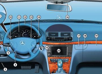
The cruise control automatically maintains the speed you set for your vehicle. Use of cruise control is recommended for driving at a constant speed for extended periods of time. You can set or resume cruise control at any speed above 20 mph (30 km/h). The cruise control function is operated by means of the cruise control lever. The cruise control lever is the uppermost lever on the left-hand side of the steering column (컄 page 22).
Controls in detail Driving systems
Warning!
The cruise control is a convenience system designed to assist the driver during vehicle operation. The driver is and must remain at all times responsible for the vehicle speed and for safe brake operation.
Only use the cruise control if the road, traffic and weather conditions make it advisable to travel at a steady speed. 앫 The use of cruise control can be danger- ous on winding roads or in heavy traffic because conditions do not allow safe driving at a steady speed.
앫 The use of cruise control can be danger- ous on slippery roads. Rapid changes in tire traction can result in wheel spin and loss of control.
앫 Deactivate the cruise control when driv-
ing in fog.
The “Resume” function should only be oper- ated if the driver is fully aware of the previ- ously set speed and wishes to resume this particular preset speed.
239
i On uphill or downhill grades, the cruise control may not be able to maintain the set speed. Once the grade eases, the set speed will be resumed. On downhill grades, the cruise control maintains the set speed with active braking action. In addition, on longer downhill grades the automatic transmission will auto- matically downshift.
Setting current speed 왘 Accelerate or decelerate to the desired
speed.
왘 Briefly lift 1 or depress 2 the cruise
control lever. The current speed is set.
왘 Remove your foot from the accelerator
pedal. Cruise control is activated.
The selected speed appears in the multi- function display for approximately 5 seconds, and the corresponding speed- ometer segments from the selected speed to the vehicle maximum speed are illumi- nated.
Controls in detail Driving systems
1 Set current or higher speed 2 Set current or lower speed 3 Cancel cruise control 4 Resume at last set speed
Warning!
The cruise control brakes automatically so that the set speed is not exceeded.
Keep in mind that the cruise control is a convenience system designed to assist the driver during vehicle operation. The driver is and must remain at all times responsible for the vehicle speed and for safe brake operation.
240
Canceling cruise control There are several ways to cancel the cruise control: 왘 Step on the brake pedal.
The cruise control is canceled. The last speed set is stored for later use.
or 왘 Briefly push the cruise control lever in
direction of arrow 3 (컄 page 240). The cruise control is canceled. The last speed set is stored for later use.
The last stored speed is canceled when you turn off the engine.
The cruise control switches off auto- matically if 앫 you step on the brake pedal. 앫 you depress the parking brake
pedal. In this case the segments in the multifunction display (컄 page 245) go out and no warning sounds.
앫 the vehicle speed is below 20 mph
(30 km/h).
앫 the ESP® is in operation or
switched off with the ESP® switch (컄 page 96).
앫 you move the gear selector lever to
position N while driving.
The segments in the multifunction dis- play (컄 page 245) go out, and an acoustic warning sounds.
Controls in detail Driving systems
Moving gear selector lever to position N while driving also cancels the cruise control. However, the gear selector lever should not be moved to position N while driving except to coast when the vehicle is in danger of skid- ding (e.g. on icy roads).
Depressing the accelerator pedal does not deactivate the cruise control. After brief acceleration (e.g. for passing), the cruise control will resume the last speed set.
241
Controls in detail Driving systems
Setting a higher speed 왘 Lift cruise control lever in direction of arrow 1 (컄 page 240) and hold it up until the desired speed is reached.
왘 Release the cruise control lever.
The new speed is set.
Setting a lower speed 왘 Depress the cruise control lever in di- rection of arrow 2 (컄 page 240) and hold it down until the desired speed is reached.
왘 Release cruise control lever.
The new speed is set.
When you use the cruise control lever to decelerate, the brake system will au- tomatically brake the vehicle if the en- gine’s braking power does not brake the vehicle sufficiently.
242
Fine adjustment in 1 mph (Canada: 1 km/h) increments
Setting to last stored speed (“Resume” function)
Faster 왘 Briefly tip the cruise control lever in di-
rection of arrow 1 (컄 page 240).
Slower 왘 Briefly tip the cruise control lever in di-
rection of arrow 2 (컄 page 240).
Warning!
The speed stored in memory should only be set again if prevailing road conditions per- mit. Possible acceleration or deceleration differences arising from returning to the pre- set speed could cause an accident and/or serious injury to you and others.
왘 Briefly pull the cruise control lever in di-
rection of arrow 4 (컄 page 240). The cruise control resumes the last set speed.
왘 Remove your foot from the accelerator
pedal.
The selected speed appears in the multi- function display for approximately 5 seconds, and the corresponding speed- ometer segments from the selected speed to the vehicle maximum speed are illumi- nated.
Distronic*
When activated, the Distronic adaptive cruise control system increases driving convenience afforded by the cruise control during travel on expressways and other major roads. 앫 If the Distronic distance sensor detects a slower moving vehicle directly ahead, your vehicle speed will be reduced so that you follow that vehicle at a preset distance.
앫 If there is no vehicle directly ahead of you, Distronic will function in the same way as cruise control (컄 page 248).
Warning!
Distronic adaptive cruise control is no sub- stitute for active driving involvement. It does not react to stationary objects, nor recog- nize or predict the curvature and lane layout or the movement of vehicles ahead. Distronic can only apply a maximum of 20% of the vehicle’s braking power.
It is the driver’s responsibility at all times to be attentive to road, traffic and weather con- ditions and to provide the steering, braking and other driving inputs necessary to retain control of the vehicle.
Warning!
Distronic is a convenience system, its speed adjustment reduction capability is intended to make cruise control more effective and usable when traffic speeds vary. It is not however, intended to, nor does it, replace the need for extreme care. The responsibili- ty for the vehicle speed and the distance to the vehicle ahead, including most impor- tantly brake operation to assure safe stop- ping distance, always rests with the driver.
Distronic cannot take street and traffic con- ditions into account.
Controls in detail Driving systems
Warning!
Distronic requires familiarity with its opera- tional characteristics. We strongly recom- mend that you review the following information carefully before operating the system.
USA only: This device complies with Part 15 of the FCC Rules. Operation is subject to the following two conditions: (1) This device may not cause harmful
interference, and
(2) this device must accept any
interference received, including interference that may cause undesired operation.
Any unauthorized modification to this device could void the user’s authority to operate the equipment.
243
Controls in detail Driving systems
Canada only: This device complies with RSS-210 of Industry Canada. Operation is subject to the following two conditions: (1) This device may not cause
interference, and
(2) this device must accept any
interference received, including interference that may cause undesired operation of the device. Any unauthorized modification to this device could void the user’s authority to operate the equipment.
Warning!
Distronic cannot take street and traffic con- ditions into account. Only use Distronic if the road, weather and traffic conditions make it advisable to travel at a steady speed.
244
Warning!
Warning!
Use of Distronic can be dangerous on slip- pery roads. Rapid changes in tire traction can result in wheel spin and loss of control.
Distronic does not act upon adverse sight distance conditions. Do not use Distronic during conditions of fog and heavy rain, snow or sleet.
Distronic cannot take weather conditions into account. Switch off Distronic or do not turn it on if: 앫 roads are slippery or covered with snow
or ice. The wheels could lose traction while braking or accelerating, and the vehicle could skid.
앫 the sensor is dirty or visibility is
diminished due to snow, rain or fog. The distance control could be impaired.
Always pay attention to traffic conditions even while Distronic is switched on. Other- wise, you may not be able to recognize dangerous situations until it is too late and could cause an accident resulting in person- al or fatal injury to you or others.
Controls in detail Driving systems
Warning!
In these situations, Distronic will continue to maintain the set speed unless deactivated.
Distronic displays in the speedometer dial
Close attention to road and traffic condi- tions is imperative at all times, regardless of whether or not Distronic is activated.
Distronic is designed and intended only to maintain a set speed and keep a set dis- tance from moving objects in front of it.
Warning!
The “Resume” function should only be oper- ated if the driver is fully aware of the previ- ously set speed and wishes to resume this particular preset speed.
Use of Distronic can be dangerous on wind- ing roads or in heavy traffic because condi- tions do not allow safe driving at a steady speed.
Distronic will not react to stationary objects in the roadway (e.g. a stopped vehicle in a traffic jam or a disabled vehicle). Distronic will also not respond to oncoming vehicles.
Switch off Distronic: 앫 when changing from the left to the right lane if vehicles are moving more slowly in the left lane
앫 when entering a turn lane or highway off
ramp
앫 in complex driving situations, such as in
highway construction zones
1 Set speed If Distronic is activated, one or two seg- ments come on around the set speed.
The vehicle speed displayed on the speedometer can briefly vary from the speed setting on the Distronic system.
245
Controls in detail Driving systems
1 Segments If Distronic detects a vehicle directly ahead, the segments (representing the difference) from the speed of the vehicle ahead to the set speed come on. If Distronic calculates that there is a dan- ger of collision: 앫 The distance warning lamp l in the
instrument cluster comes on red. 앫 An intermittent warning sounds.
246
왘 Immediately brake the vehicle to avoid
a collision. Under no circumstances should the driver await the intermittent warning sound before braking. See the follow- ing warning note. The intermittent warning sound ceases and the red distance warning lamp l goes out when the neces- sary distance to the vehicle ahead is again established.
Warning!
An intermittent warning sounds and the distance warning lamp l in the instru- ment cluster is illuminated if the Distronic system calculates that the distance to the vehicle ahead and your vehicle’s current speed indicate that Distronic will not be ca- pable of slowing the vehicle sufficiently to maintain the preset following distance, which creates a danger of a collision.
Immediately brake the vehicle to increase the distance to the vehicle in front of you. The warning sound is intended as a final cau- tion that you have not interceded with your own braking inputs to avoid a potentially dangerous situation. Do not wait for the op- eration of the warning signal to intercede with your own braking, as that will result in potentially dangerous emergency braking which will not always result in an impact be- ing avoided.
Tailgating increases the risk of an accident.
Warning!
Distronic brakes your vehicle with a maxi- mum deceleration of 6.5 ft/s2 (2 m/s2). This corresponds to about 20% of the maxi- mum deceleration ability of your vehicle.
Distronic brakes the vehicle in an effort to restore the preset distance or to maintain the speed.
Distronic menu in the control system In the Distronic menu you can read the cur- rent settings for Distronic. What appears in the multifunction display depends on whether Distronic and the distance warn- ing function are turned on or off. 왘 Press button è or ÿ repeatedly until you see one of the following dis- plays.
Controls in detail Driving systems
Distronic deactivated When Distronic is deactivated you will see the standard display of Distronic in the multifunction display.
1 Vehicle ahead, if detected 2 Actual distance to vehicle ahead 3 Preset distance threshold to vehicle
ahead
4 Your vehicle 5 Symbol for activated distance warning
function
247
Controls in detail Driving systems
Distronic activated If you turn Distronic on, you will see the set speed in the multifunction display for about 5 seconds. When Distronic is activated, you will see the following display in the multifunction display.
Cruise control lever The Distronic system is operated by means of the cruise control lever. The cruise control lever is the uppermost lever on the left-hand side of the steering column.
1 Distronic activated
248
1 Set current or higher speed 2 Set current or lower speed 3 Deactivate Distronic 4 Resume at last set speed
Activating Distronic You can activate Distronic if 앫 you are driving between 20 mph
(30 km/h) and 110 mph (180 km/h)
앫 the ESP® is activated (컄 page 93) If Distronic has not been activated after pressing the cruise control lever you will see the message --- in the multifunction display. In the following cases you cannot activate Distronic 앫 up to 2 minutes after starting the en-
gine
앫 when you brake 앫 if you have set the parking brake 앫 if the gear selector lever is in
position P, R or N
앫 if the ESP® is switched off
Controls in detail Driving systems
Setting the current speed 왘 Accelerate or decelerate to the desired
speed.
왘 Briefly lift or depress the cruise control
lever. The current speed is set.
왘 Remove your foot from the accelerator
pedal.
If you do not take your foot off the accelerator completely, the following message will appear in the multifunc- tion display:
Distronic override The distance to a slower moving vehi- cles in front of you will not be set. Your vehicle speed will then be determined only by the accelerator pedal position.
Setting a higher speed 왘 Briefly tip the cruise control lever in di- rection of arrow 1 (컄 page 248) to in- crease vehicle speed in increments of 5 mph (Canada: 10 km/h). The new speed is set. The stored speed is displayed in the multifunction display for approximately 5 seconds (컄 page 248), and one or two segments around the stored speed come on in the speedometer (컄 page 245).
Setting a lower speed 왘 Briefly tip the cruise control lever in di- rection of arrow 2 (컄 page 248) to de- crease vehicle speed in increments of 5 mph (Canada: 10 km/h). The new speed is set. The stored speed is displayed in the multifunction display for approximately 5 seconds (컄 page 248), and one or two segments around the stored speed come on in the speedometer (컄 page 245).
Depressing the accelerator pedal does not deactivate Distronic. After brief ac- celeration (e.g. for passing), the cruise control will resume the last speed set.
When you use the cruise control lever to decelerate, the brakes will be ap- plied to support deceleration. In addition, the transmission will auto- matically downshift on long downhill grades.
249
Controls in detail Driving systems
Fine adjustment in 1 mph (Canada: 1 km/h) increments
Setting to last stored speed (“Resume” function)
Faster 왘 Briefly tip the cruise control lever in di-
rection of arrow 4 (컄 page 248).
Warning!
The speed stored in memory should only be set again if prevailing road conditions per- mit. Possible acceleration or deceleration differences arising from returning to the pre- set speed could cause an accident and/or serious injury to you and others.
왘 Briefly tip the cruise control lever in di-
rection of arrow 4 (컄 page 248). Distronic is activated and set to the last stored speed.
왘 Remove your foot from the accelerator
pedal.
Deactivating Distronic There are several ways to deactivate the Distronic system: 왘 Briefly tip the cruise control lever in di-
rection of arrow 3 (컄 page 248).
or 왘 Step on the brake pedal.
Distronic will be deactivated. The last speed set will be stored into memory.
The following message will appear in the multifunction display for approxi- mately 5 seconds:
Distronic off The last stored speed is deleted when you turn off the engine.
250
Distronic deactivates automatically when 앫 you set the parking brake 앫 you drive slower than 20 mph
(30 km/h)
앫 the ESP® is active (컄 page 93) or you
deactivate the ESP®
앫 you move the gear selector lever into
position N A signal will sound. The Distronic off message appears in the multifunction display for approximately 5 seconds.
Setting the following distance in Distronic You can set the specified following dis- tance for Distronic by varying the time set- ting between 1.0 and 2.0 seconds. Using this time setting and the current speed of your vehicle, Distronic calculates and sets the required following distance to the vehi- cle ahead. The set distance will be shown in the multifunction display. The thumbwheel for making the time set- ting is located on the lower section of the center console.
Warning!
Warning!
Distronic switches off and releases the brakes when the vehicle decelerates below the minimum speed of 20 mph (30 km/h) by operation of the system. At that time the driver must apply the brakes in order to re- duce vehicle speed further or bring it to a stop.
It is up to the driver to exercise discretion to select the appropriate setting given road conditions, traffic, driver’s preferred driving style and applicable laws and driving recom- mendations for safe following distance.
Controls in detail Driving systems
1 Distance warning function on/off
switch
2 Indicator lamp 3 Thumbwheel for setting distance
Increasing distance Increasing the distance setting tells Distronic to maintain a greater following distance to the vehicle ahead. 왘 Turn thumbwheel 3 towards ¯.
251
Activating 왘 Press switch 1.
Indicator lamp 2 on the switch comes on. A loudspeaker symbol appears in the multifunction display (컄 page 248).
Deactivating 왘 Press switch 1.
Indicator lamp 2 on the switch goes out. No loudspeaker symbol appears in the multifunction display.
Controls in detail Driving systems
Decreasing distance Decreasing the distance setting tells Distronic to maintain a smaller following distance to the vehicle ahead. 왘 Turn thumbwheel 3 towards ®.
Distance warning function When Distronic is deactivated, this func- tion will continue to warn you when recog- nizing a stationary obstacle or a slower vehicle moving in the vehicle’s path and the danger of a collision exists: 앫 The distance warning lamp l in the
instrument cluster comes on.
앫 An intermittent warning will sound if
necessary.
If these warnings are issued, you must brake manually to maintain a safe distance and avoid a collision with the vehicle ahead. When pressing the brake pedal, the warn- ing sound ceases. The warning sound will also cease when the distance to the vehi-
252
cle ahead is sufficient again without apply- ing the brakes. In this case, the distance warning lamp will also go out.
Warning!
If the distance warning lamp l in the in- strument cluster comes on while driving and/or an intermittent warning sounds, im- mediate attention on the part of the driver is required. As required by the traffic situation, apply the brakes and navigate around a pos- sible obstacle. However, do not drive by re- lying on the distance warning function, as this will result in an emergency braking ap- plication. Especially depending on road sur- face conditions and driver reaction, this will not always enable you to avoid a collision.
Complex driving situations are not al- ways fully recognized by Distronic. This could result in wrong or missing dis- tance warnings.
Driving with Distronic This section describes a number of driving situations where special precaution is re- quired on the part of the driver. Be pre- pared to brake in such situations. This will deactivate the Distronic system.
Warning!
Distronic works to maintain the speed se- lected by the driver unless a moving obsta- cle proceeding directly ahead of it in the same travel direction is detected (e.g. fol- lowing another vehicle ahead of you at a dis- tance set by Distronic). This means that: 앫 Your vehicle can pass another vehicle
after you change lanes.
앫 While in a sharp turn or if the vehicle in front is in a sharp turn, Distronic could lose sight of a vehicle traveling in front of it, then your vehicle could accelerate to the previously selected speed.
Distronic regulates only the distance be- tween your vehicle and those directly ahead of it, but does not register stationary objects in the road, e.g.: 앫 a stopped vehicle in a traffic jam 앫 a disabled vehicle 앫 an oncoming vehicle The driver must always be on the alert, ob- serve all traffic and intercede as required by steering or braking the vehicle.
Warning!
Distronic should not be used in snowy or icy road conditions.
Controls in detail Driving systems
The most likely cause for a malfunctioning system is a dirty sensor (located behind the hood grille), especially at times of snow and ice or heavy rain. In such a case, Distronic will switch off, and the message Distronic Currently unavailable See Operator’s Manual appears in the multifunction display. For cleaning and care of the Distronic sen- sor, see “Cleaning the Distronic* system sensor cover” (컄 page 366).
If the message Distronic Currently unavailable See Operator’s Manual disappears during driving and the last speed stored flashes for approximately 5 seconds, the dirt (e.g. slush) has dis- solved; Distronic works again.
253
Controls in detail Driving systems
Turns and bends
Offset driving
Lane changing
In turns or bends, Distronic may not detect a moving vehicle in front, or it may detect one too soon. This may cause your vehicle to brake late or unexpectedly.
A vehicle traveling in your lane but offset from your direct line of travel may not be detected by Distronic. There will be insuffi- cient distance to the vehicle ahead.
Distronic has not yet detected the vehicle changing lanes. There will be insufficient distance to the lane-changing vehicle.
254
Narrow vehicles
Airmatic DC (Dual Control)*
Airmatic automatically selects the opti- mum suspension tuning and ride height for your vehicle. The Airmatic consists of two components: 앫 Adaptive Damping System (ADS) 앫 Vehicle level control The ADS automatically selects the opti- mum damping for the respective driving conditions. At the same time the suspen- sion is set to either Sport 1, Sport 2 or Comfort.
Because of their narrow profile, the vehi- cles traveling near the outer edges of the lane have not yet been detected by Dis- tronic. There will be insufficient distance to the vehicles ahead.
Controls in detail Driving systems
Suspension tuning The suspension tuning is set according to: 앫 Your driving style 앫 Road surface conditions 앫 Your choice of suspension style,
Sport 1, Sport 2 or Comfort, which you select using the damping button 1 (컄 page 256). The following suspension styles are available: 앫 Comfort
Both indicator lamps 2 (컄 page 256) are off.
앫 Sport 1
One indicator lamp 2 (컄 page 256) is on.
앫 Sport 2
Both indicator lamps 2 (컄 page 256) are on.
255
Controls in detail Driving systems
1 Damping button 2 Indicator lamps 왘 Start the engine. 왘 Press the damping button 1 until the
desired suspension style is set.
256
If you have selected the Comfort sus- pension tuning, the vehicle lowers slightly when you lock it within approx- imately 60 seconds after switching off the engine. When parking, make sure that your vehicle cannot come into con- tact with other objects, such as a curb, while lowering. Your vehicle could oth- erwise be damaged.
The selected suspension style is stored in memory, even after the SmartKey is removed from the starter switch.
Vehicle level control Your vehicle automatically adjusts its ride height to 앫 increase vehicle safety 앫 reduce fuel consumption The following vehicle chassis ride heights can be selected: 앫 Normal 앫 Raised The vehicle chassis ride height is raised or lowered according to the selected level setting and to the vehicle speed: 앫 At a speed exceeding approximately
68 mph (110 km/h) with normal level set or exceeding 75 mph (120 km/h) with raised level set, the ride height is reduced automatically. The table on the next page provides an overview of the vehicle levels.
앫 With decreasing speed, the ride height
is again raised to the normal level.
i These height adjustments are so small that you may not notice any change.
Select the “Raised” level only when re- quired by current driving conditions. Oth- erwise 앫 handling may be impaired 앫 fuel consumption may increase
Warning!
To help avoid personal injury, keep hands and feet away from wheel housing area, and stay away from under the vehicle when low- ering the vehicle chassis.
Controls in detail Driving systems
257
Controls in detail Driving systems
The following vehicle level settings can be selected when the vehicle is stationary and the engine is running:
Indicator lamp Suspension
Use for
Vehicle level when stationary Normal
Lamp off
tuning Comfort
Normal
Raised
Lamp off
Sport 1 or 2
Lamp on
Comfort
Raised
Lamp on
Sport 1 or 2
258
Ride height increase over normal None
Automatic lowering
Max. approx. 0.4 in (10 mm)
None
Max. approx. 0.6 in (15 mm)
Approx. 0.8 in (20 mm) Max. approx. 1.2 in (30 mm)
Approx. 0.8 in (20 mm) Max. approx. 1.4 in (35 mm)
For driving on normal roads For driving on normal roads For driving on rough roads or with snow chains For driving on rough roads or with snow chains
i At a speed of approximately above 75 mph (120 km/h) or if the speed amounts to between 50 mph (80 km/h) and 75 mph (120 km/h) for approximately five minutes, the set- ting raised is canceled. The indicator lamp 2 in the button goes out. If you do not drive in this speed range, the raised level remains stored even if the SmartKey is removed from the starter switch.
The button is located in the lower section of the center console.
1 Vehicle level control button 2 Indicator lamp 왘 Start the engine (컄 page 36). 왘 Briefly press button 1 to change from normal level to raised level. When vehi- cle is at raised level, pressing the but- ton will return the vehicle to normal level. When raised level is set, indicator lamp 2 in the button comes on. When normal level is set, indicator lamp 2 in the button goes out.
Controls in detail Driving systems
259
Controls in detail Loading
Split rear bench seat
Folding the backrest forward
To expand the cargo compartment, you can fold down the left and right rear seat backrests. The two sections can be folded down sep- arately to enlarge the cargo compartment.
You must always release the seat cush- ion and fold it up before folding the seat backrests forward. The upholstery on the backrest may otherwise be dam- aged.
If tall persons have occupied the driver’s and front passenger seats, it may be necessary to move these seats forward slightly in order to fold the rear seat backrests forward.
Warning!
When expanding the cargo compartment, al- ways fold the seat cushions fully forward.
Unless you are transporting cargo, the back- rests must remain properly locked in the up- right position.
In an accident, during hard braking or sud- den maneuvers, loose items will be thrown around inside the vehicle, and cause injury to vehicle occupants unless the items are securely fastened in the vehicle.
Always use the cargo tie down rings (컄 page 264).
260
1 Release catch 2 Seat cushion 왘 Pull release catch 1 and use it to pull
seat cushion 2 up.
1 Release catch 2 Seat backrest 왘 Pull release catch 1 up.
The seat backrest is released and the head restraints fold back.
왘 Fold the seat backrest 2 forward.
i If the rear center seat is to be occupied while driving, it may be necessary to fold the seat belt buckle up again.
Returning seat backrest to original po- sition
왘 Swing seat cushion 1 to the rear and press down from the rear of the cush- ion until it audibly engages.
왘 Swing the head restraint forward by
hand until it engages.
1 Seat cushion 2 Seat backrest 왘 Swing seat backrest 2 to the rear until
it engages.
Controls in detail Loading
Warning!
Always lock backrest in its upright position when rear seat bench is occupied, or the ex- tended cargo compartment is not in use. Check for secure locking by pushing and pulling on the backrest.
In an accident, during hard braking or sud- den maneuvers, loose items will be thrown around inside the vehicle, and cause injury to vehicle occupants unless the items are securely fastened in the vehicle.
To help avoid personal injury during a colli- sion or sudden maneuver, exercise care when transporting cargo.
261
Controls in detail Loading
Adjusting seat backrest position
왘 Pull right seat release catch 1 up and
Expanding the cargo compartment
fold seat backrest forward.
왘 With the seat backrest released, pull
release catch 1 up again.
왘 Pull left seat release catch 1 up and
fold seat backrest forward.
왘 With the seat backrest released, pull
release catch 1 up again.
왘 Fold left seat backrest to the rear until
it engages.
왘 Fold right seat backrest to the rear until
it engages. The seat backrests are now in the alter- native position.
Removing the rear seat cushions will pro- vide you with a larger, flat cargo compart- ment. 왘 Fold the seat cushions forward
(컄 page 260).
1 Release lever 왘 Pull seat cushion release lever 1 and remove the seat cushion by pulling it upward.
왘 Remove the head restraints
(컄 page 132).
1 Release catch 2 Seat backrest
The seat backrests can be placed in an alternative upright position. This cre- ates a larger cargo compartment area or provides for improved seating com- fort on the folding bench seat, if re- quired.
262
! Leave the seat cushion hinge in this po- sition. The upholstery could be dam- aged if you fold the hinge back.
Loading instructions
왘 Fold the seat backrest forward
(컄 page 260).
The total load weight including vehicle oc- cupants and luggage/cargo should not ex- ceed the load limit or vehicle capacity weight indicated on the corresponding placard located on the driver’s door B-pil- lar.
Controls in detail Loading
The handling characteristics of a fully load- ed vehicle depend greatly on the load dis- tribution. It is therefore recommended to load the vehicle according to the illustra- tions shown, with the heaviest items being placed towards the front of the vehicle. Always place items being carried against front or rear seat backrests, and fasten them as securely as possible. The heaviest portion of the cargo should al- ways be kept as low as possible since it in- fluences the handling characteristics of the vehicle.
263
Rear seat There is a cargo tie-down ring located on each side of the footwell under the rear seat.
Controls in detail Loading
Warning!
Cargo tie-down rings
Always fasten items being carried as secure- ly as possible.
In an accident, during hard braking or sud- den maneuvers, loose items will be thrown around inside the vehicle and can cause in- jury to vehicle occupants unless the items are securely fastened in the vehicle.
To help avoid personal injury during a colli- sion or sudden maneuver, exercise care when transporting cargo. Put luggage or car- go in the cargo compartment if possible. Do not pile luggage or cargo higher than the seat backs.
Never drive vehicle with tailgate open. Deadly carbon monoxide (CO) gases may enter vehicle interior resulting in uncon- sciousness and death.
264
Four rings 1 are located in the cargo com- partment. 왘 Carefully secure cargo by applying
even load on all rings with rope of suffi- cient strength to hold down the cargo. Always follow loading instructions (컄 page 263).
Cargo management system* (Canada only)
Your vehicle may be equipped with a cargo management system and accompanying accessories which enable you to utilize your cargo compartment in a variety of ways. You can store the cargo manage- ment system in the pouch that comes with the vehicle.
The pouch and telescoping rod can be placed in the storage box in the cargo compartment.
1 Cargo rails
Controls in detail Loading
Inserting the mounting elements into the cargo rails
1 Cargo rail 2 Mounting element You can move the mounting element to various engaging points on the cargo rail and fix it in place. These engaging points are located 2 inches apart from one another on the cargo rail and are indicated by markings.
컄컄
265
Inserting the cargo tie-down ring in the mounting element
Warning!
The cargo tie-down rings should be subject to equal loads. Make sure to comply with the information provided in the loading in- structions (컄 page 263).
왘 Turn mounting element 2 in the cargo
rail to N.
왘 Insert cargo tie-down ring 1 into
mounting element 2.
왘 Turn mounting element 2 until it en-
gages in the ‹ position. You should be able to feel the mounting element engage in the cargo rail.
1 Cargo tie-down ring 2 Mounting element
Controls in detail Loading
컄컄
You can turn the mounting element in the cargo rail to four positions: ‹ To lock the mounting element. N To insert or remove the cargo tie-down ring, the belt reel or the telescoping rod.
L To insert or remove the mount-
ing element.
S To move the mounting element
to the next engaging point.
왘 Turn mounting element 2 to L. 왘 Insert mounting element 2 in cargo
rail 1.
왘 Turn mounting element 2 until it en-
gages in the ‹ position. You should be able to feel the mounting element engage in the cargo rail.
266
Belt reel
왘 Insert two mounting elements 2 into a
Telescoping rod
Controls in detail Loading
cargo rail.
왘 Turn mounting element 2 in the cargo
rail to N.
왘 Insert belt reel 1 into mounting ele-
ment 2.
왘 Turn mounting element 2 in the cargo
rail until it engages in the ‹ posi- tion. You should be able to feel the mounting element engage in the cargo rail.
왘 Press locking button 3 on the belt reel and pull cargo net out in direction of ar- row.
왘 Place load between the cargo net and
the side wall of the cargo compart- ment.
왘 Press locking button 3 on belt reel. With the other hand, slowly pull net over load until it is taut.
1 Belt reel 2 Mounting element 3 Locking button
The belt reel can be used to tighten light-weight loads against the side wall of the cargo compartment, thus secur- ing them from slipping.
1 Telescoping rod 2 Mounting element
The telescoping rod can be used to tighten the load against the rear seats so as to secure it from slipping.
267
Controls in detail Loading
왘 Insert one mounting element 2 into
each cargo rail.
Storage box in cargo compartment (Canada only)
왘 Turn mounting element 2 in cargo rail
to N.
왘 Insert telescoping rod 1 into mount-
ing element 2.
왘 Turn mounting element 2 in cargo rail
until it engages in the ‹ position. You should be able to feel the mounting element engage in the cargo rail.
Warning!
When you are using the storage box in the cargo compartment, the backrests of the seats in front of it must be completely en- gaged to the rear, and the twin roller blind must be installed.
Do not exceed the storage box’s maximum load of 44 lbs (20 kg), as it could otherwise become detached during an accident or sharp braking maneuvers, and could injure you or other passengers.
When leaving the vehicle, always remove the SmartKey or the SmartKey with KEYLESS-GO* from the starter switch, take it with you, and lock the vehicle. Do not leave children unattended in the vehicle, or with access to an unlocked vehicle. Unsu- pervised use of vehicle equipment may cause an accident and/or serious personal injury.
1 Storage box
268
Controls in detail Loading
The storage box in the cargo compart- ment is covered by the rear bench seat and can hold a maximum of 44 lbs (20 kg) cargo.
Twin roller blind
The twin roller blind contains a cargo net and a cargo compartment cover. It is located on the seat backrest of the rear bench seat.
왘 Fold rear seat backrest to the rear
(컄 page 261).
Removing the storage box 왘 Fold rear seat backrests forward
(컄 page 260).
왘 Slide locking hooks of storage box for-
ward out of the retainers.
왘 Pull storage box to the rear and remove
it from cargo compartment.
왘 Fold rear seat backrest to the rear
(컄 page 261).
Cargo net
Warning!
The cargo net cannot hold back heavy loads. The transported load should therefore al- ways be tied down.
Objects which are insufficiently secured could otherwise injure you if they are thrown around in the event of an accident, during hard braking or steering maneuvers.
Installing the storage box 왘 Fold rear seat backrests forward
(컄 page 260).
왘 Insert storage box from behind into
cargo compartment with the opening pointing in direction of travel.
왘 Press locking hooks of storage box into the space between the rear seat back- rest and the cargo compartment. 왘 Fold rear seat backrest to the rear
(컄 page 261).
The storage box is additionally held in place from above by the twin roller blind.
Loading the storage box 왘 Fold rear seat backrests forward
(컄 page 260).
왘 Fill storage box with cargo through the
opening on the front side.
269
Cargo compartment cover The cargo compartment cover unlocks automatically while the tailgate is open- ing/closing and is automatically raised/ lowered.
When loading the vehicle, make sure not to load the cargo compartment over the lower edge of the side win- dows. The twin roller blind could otherwise be damaged when the tailgate is being closed.
It is therefore unnecessary to roll up the cargo compartment cover before loading and unloading.
1 Cargo compartment cover
Rolling up the cargo compartment cover 왘 Unhook cargo compartment cover from its anchorages on the left and right sides.
왘 Slowly guide cargo compartment cover
back until it stops.
Controls in detail Loading
1 Cargo net 2 Mountings for cargo net 왘 Pull cargo net 1 up and hook it onto
mountings 2.
You can use the cargo net even when the rear seat backrest is folded for- ward. The cargo net should then be hooked onto the front mountings.
270
Removing the twin roller blind 왘 Roll up cargo net and cargo compart-
ment cover.
왘 Fold both rear seat cushions forward
(컄 page 260).
왘 Push twin roller blind to the left out of its anchorage on the rear seat backrest and remove it.
Controls in detail Loading
271
Controls in detail Useful features
Storage compartments
Glove box
Storage compartment in the center console (no CD changer* installed)
Warning!
To help avoid personal injury during a colli- sion or sudden maneuver, exercise care when storing objects in the vehicle. Put lug- gage or cargo in the cargo compartment if possible. Do not pile luggage or cargo higher than the seat backs.
Luggage nets cannot secure hard or heavy objects.
Keep compartment lids closed. This will help to prevent stored objects from being thrown around and injuring vehicle occupants dur- ing an accident.
272
1 Glove box lid release 2 Compartment for mobile
phone/glasses
Opening the glove box 왘 Push glove box lid release 1.
The glove box lid opens downward.
Closing the glove box 왘 Push glove box lid up to close.
Close the compartment for glasses 2 first before closing the glove box.
1 Opening/closing button 왘 Press button 1 to open.
The control panel swings out upward and the storage compartment extends out.
Never place any medications in the storage compartment. If there is a pow- er failure, the storage compartment cannot be opened.
왘 Press button 1 to close.
Storage compartment in the rear cen- ter console
Ruffled storage bags
왘 Briefly press the top of the compart-
ment. It extends automatically.
Ruffled storage bags are located on the back of the front seats.
Controls in detail Useful features
Warning!
Do not place objects with a combined weight of more than 4.4 lbs (2 kg) into the ruffled storage bag. Otherwise, the Occu- pant Classification System OCS (컄 page 81) may not be able to properly approximate the occupant weight category.
The ruffled storage bag is intended for stor- ing light-weight items only.
Heavy objects, objects with sharp edges or fragile objects may not be transported in the ruffled storage bag. In an accident, during hard braking, or sudden maneuvers, they could be thrown around inside the vehicle and cause injury to vehicle occupants.
The ruffled storage bag cannot protect transported goods in the event of an acci- dent.
273
Controls in detail Useful features
Parcel net in front passenger footwell
Warning!
Cup holders
The parcel net is intended for storing light-weight items only.
Heavy objects, objects with sharp edges or fragile objects may not be transported in the parcel net. In an accident, during hard brak- ing, or sudden maneuvers, they could be thrown around inside the vehicle and cause injury to vehicle occupants.
The parcel net cannot protect transported goods in the event of an accident.
A small convenience parcel net is located in the front passenger footwell. It is for small and light items, such as road maps, mail, etc.
Warning!
In order to help prevent spilling liquids on vehicle occupants and/or vehicle equip- ment, only use containers that fit into the cup holder. Use lids on open containers and do not fill containers to a height where the contents, especially hot liquids, could spill during braking, vehicle maneuvers, or in an accident. Liquids spilled on vehicle occu- pants may cause serious personal injury. Liquids spilled on vehicle equipment may cause damage not covered by the Mercedes-Benz Limited Warranty.
When not in use, keep the cup holder closed. An open cup holder may cause injury to you or others when contacted during braking, vehicle maneuvers, or in an acci- dent.
274
Keep in mind that objects placed in the cup holder may come loose during braking, vehi- cle maneuvers, or in an accident and be thrown around in the vehicle interior. Ob- jects thrown around in the vehicle interior may cause an accident and/or serious per- sonal injury.
Storage compartment with cup holder in the center armrest The storage compartment in the center armrest contains a removable dual cup holder.
Opening storage compartment
1 Cover 왘 Slide cover 1 in direction of arrow.
Controls in detail Useful features
2 Dual cup holder 3 Telephone* compartment
Closing storage compartment 왘 Slide cover 1 back.
The cup holder can be removed to in- crease storage space and for cleaning. Clean the cup holder only with clear, lukewarm water. Make sure to insert the cup holder in the guides when reinstalling it (컄 page 276).
275
Controls in detail Useful features
Removing cup holder
Reinstalling cup holder
Rear cup holder
1 Dual cup holder 2 Locking pins 왘 Move both locking pins 2 in direction
of arrows.
왘 Take cup holder 1 out upward.