- 2007 Mercedes-Benz CLS Class Owners Manuals
- Mercedes-Benz CLS Class Owners Manuals
- 2011 Mercedes-Benz CLS Class Owners Manuals
- Mercedes-Benz CLS Class Owners Manuals
- 2010 Mercedes-Benz CLS Class Owners Manuals
- Mercedes-Benz CLS Class Owners Manuals
- 2008 Mercedes-Benz CLS Class Owners Manuals
- Mercedes-Benz CLS Class Owners Manuals
- 2009 Mercedes-Benz CLS Class Owners Manuals
- Mercedes-Benz CLS Class Owners Manuals
- 2012 Mercedes-Benz CLS Class Owners Manuals
- Mercedes-Benz CLS Class Owners Manuals
- 2006 Mercedes-Benz CLS Class Owners Manuals
- Mercedes-Benz CLS Class Owners Manuals
- Download PDF Manual
-
Do not drive the vehicle without the seat head restraints. Head restraints are intend- ed to help reduce injuries during an acci- dent.
You cannot remove the active head re- straint on the driver’s and front passen- ger’s seats.
118
For removal of the active head restraints we recommend that you contact an autho- rized Mercedes-Benz Center.
i Adjust the head restraint in such a way that it is as close to the head as possible.
For information on head restraint adjust- ment, see “Seat adjustment” (컄 page 42). For information on active head restraints, see “Active head restraints” (컄 page 81).
Rear seat head restraints
Warning!
For safety reasons, always drive with the rear head restraints in the upright position when the rear seats are occupied.
Keep the area around head restraints clear of articles (e.g. clothing) to not obstruct the folding operation of the head restraints.
Warning!
For your protection, drive only with properly positioned head restraints.
Adjust head restraint so that the head re- straint supports the back of the head at eye level. This will reduce the potential for injury to the head and neck in the event of an ac- cident or similar situation.
Do not drive the vehicle without the seat head restraints. Head restraints are intend- ed to help reduce injuries during an acci- dent.
Do not interchange head restraints from front and rear seat.
i The rear seat head restraints cannot be ad- justed.
Folding head restraints back The rear seat head restraints can be folded backward for increased visibility.
Placing head restraints upright
Lumbar support
The curvature of the front seats can be ad- justed to help enhance lower back support and seating comfort.
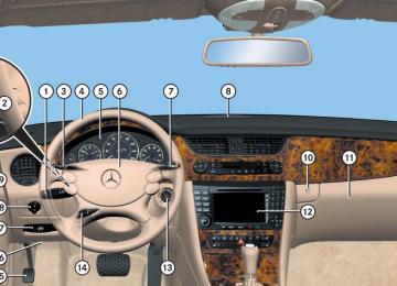
Controls in detail Seats
1 Head restraint release switch 왘 Switch on the ignition (컄 page 38). 왘 Press the symbol-side on rocker switch 1 to release the head re- straints. The head restraints will fold backward.
왘 Pull the head restraint forward until it
locks into position.
! Make sure the head restraints engage when placing them upright. Otherwise their protective function cannot be assured.
1 Adjustment lever 왘 Move adjustment lever 1 in direction of the arrows until you have reached a comfortable seating position.
119
Controls in detail Seats
Multicontour seat*
The multicontour seat has a movable seat cushion and inflatable air cushions built into the backrest to provide additional lum- bar and side support. The seat cushion movement, backrest cushion height and curvature can be con- tinuously varied with switches right side of the seat on the driver side, or the left side of the seat on the passenger side.
120
1 Seat cushion depth 2 Backrest bottom 3 Backrest center 4 Backrest side bolsters 왘 Switch on the ignition (컄 page 38).
Seat cushion depth 왘 Adjust the seat cushion depth to the
length of your upper leg using switch 1.
Backrest contour 왘 Adjust the contour of the backrest to
the desired position using æ or ç.
왘 Move the backrest support cushion to the bottom by using button 2 or to the center by using button 3.
Backrest side bolsters 왘 Adjust the side bolsters so that they
provide good lateral support using switch 4.
i If, after a period of time, the seat no longer provides the desired contour, then repeat the ad- justment procedure.
Seat heating*
The red indicator lamps on the switch show the heating level selected.
Level
off
Three indicator lamps on (highest level). The seat heating automatically switches to level 2 after approxi- mately 5 minutes. Two indicator lamps on. The seat heating automatically switches to level 1 after approxi- mately 10 minutes. One indicator lamp on (lowest level). The seat heating automatically switches off after approximately 20 minutes. No indicator lamp on.
1 Front seat heating switch
1 Rear seat heating switch (Canada only) 왘 Switch on the ignition (컄 page 38).
Controls in detail Seats
Switching seat heating on 왘 Press switch 1.
Three red indicator lamps in the switch come on.
왘 Continue pressing switch 1 until de-
sired seat heating level is reached.
Switching seat heating off 왘 Press switch 1 repeatedly until all in-
dicator lamps go out.
i If one or more of the lamps on the seat heat- ing switch are flashing, there is insufficient volt- age available since too many electrical consumers are turned on. The seat heating switches off automatically. The seat heating will switch back on again auto- matically as soon as sufficient voltage is avail- able.
121
Controls in detail Seats
Seat ventilation*
The blue indicator lamps on the switch show the ventilation level selected.
Level
off
Three indicator lamps on (highest level). Two indicator lamps on. One indicator lamp on (lowest level). No indicator lamp on.
i The seat ventilation for the driver’ seat can be activated using summer opening feature (컄 page 208).
122
1 Seat ventilation switch 왘 Switch on the ignition (컄 page 38).
Switching seat ventilation on 왘 Press switch 1 repeatedly until the
desired ventilation level is set. One or more blue indicator lamps on the switch show the selected ventila- tion level.
Switching seat ventilation off 왘 Press switch 1 repeatedly until all in-
dicator lamps go out.
i If one or more of the lamps on the seat ven- tilation switch are flashing, there is insufficient voltage available since too many electrical con- sumers are turned on. The seat ventilation switches off automatically. The seat ventilation will switch back on again au- tomatically as soon as sufficient voltage is avail- able.
With the memory function you can store up to three different configurations. Each stored position on the driver’s side in- cludes the following settings: 앫 Seat position 앫 Multicontour seat*: previously saved
setting
앫 Steering wheel position 앫 Exterior rear view mirror positions
Controls in detail Memory function
Warning!
Do not activate the memory function while driving. Activating the memory function while driving could cause the driver to lose control of the vehicle.
Each stored position on the passenger side includes the following settings: 앫 Seat position 앫 Multicontour seat*: previously saved
setting
왔 Memory function Prior to operating the vehicle, the driver should check and adjust the seat height, seat position fore and aft, and seat back- rest angle if necessary, to ensure adequate control, reach and comfort. The head re- straint should also be adjusted for proper height. See also the section on air bags (컄 page 66) for more information on prop- er seat positioning. In addition, adjust the steering wheel to ensure adequate control, reach, operation and comfort. Both the interior and exterior rear view mirrors should be adjusted for adequate rear vision. Fasten seat belts. Infants and small chil- dren should be seated in a properly se- cured restraint system that complies with U.S. Federal Motor Vehicle Safety Stan- dards 213 and 225 and Canadian Motor Vehicle Safety Standards 213 and 210.2.
123
Storing positions into memory
Recalling positions from memory
왘 Adjust the seats, steering wheel and exterior rear view mirrors to the de- sired position (컄 page 41).
왘 Press memory button M. 왘 Release memory button M and press memory position button 1, 2 or 3 with- in 3 seconds. When the settings are stored to the se- lected position, an acknowledgement signal sounds.
! Do not operate the power seats using the memory button if the seat backrest is in an ex- cessively reclined position. Doing so could cause damage to front or rear seats. First move seat backrest to an upright position. 왘 Press and hold memory position
button 1, 2 or 3 until the seat, steering wheel and exterior rear view mirrors have completely moved to the stored positions.
i Releasing the memory position button stops movement to the stored positions immediately. The multicontour seat* will continue to be ad- justed.
Controls in detail Memory function
1, 2, 3
Memory button Stored position button
124
Controls in detail Memory function
Storing exterior rear view mirror parking position
For easier parking, you can adjust the pas- senger-side exterior rear view mirror so that you can see the right rear wheel as soon as you engage reverse gear R. For information on activating the parking position, see “Activating exterior rear view mirror parking position” (컄 page 184).
왘 Stop the vehicle. 왘 Switch on the ignition (컄 page 38). 왘 Press button 1.
The passenger-side exterior rear view mirror is selected.
왘 Adjust the exterior rear view mirror
with button 2 so that you see the rear wheel and the road curb.
왘 Press memory button M 3. 왘 Within 3 seconds, press bottom of ad-
justment button 2. The parking position is stored if the mirror does not move.
i If the mirror does move, repeat the above steps. After the setting is stored, you can move the mirror again.
1 Passenger-side exterior rear view
mirror button
2 Adjustment button 3 Memory button
125
Controls in detail Lighting
For information on how to switch on the headlamps and use the turn signals, see “Switching on headlamps” (컄 page 55) and see “Turn signals” (컄 page 55).
i If you drive in countries where vehicles drive on the other side of the road than the country where the vehicle is registered, you must have the headlamps modified for symmetrical low beams. Relevant information can be obtained at any authorized Mercedes-Benz Center.
i Vehicles equipped with active Bi-Xenon* headlamps: The active Bi-Xenon headlamps monitor your steering angle and driving speed, then automatically shift their beams to either side to better follow the curvature of the road ahead, increasing usable illumination over con- ventional headlamps.
126
Exterior lamp switch
Exterior lamp switch
1 ‚ Standing lamps, left (turn left two
stops)
2 ˆ Standing lamps, right (turn left
one stop)
3 M Off
Daytime running lamp mode (컄 page 128)
4 U Automatic headlamp mode
Daytime running lamp mode (컄 page 128)
5 C Parking lamps (also tail lamps, li- cense plate lamps, side marker lamps, instrument panel lamps) 6 B Low beam headlamps or high
beam headlamps 7 ‡ Front fog lamps 8 † Rear fog lamp
i If you hear a warning signal you have forgot- ten to switch off the low beam headlamps or the parking lamps before opening the driver’s door. In addition the message Switch Off Lights appears in the multifunction display. Switch off the low beam headlamps or the park- ing lamps. If the message Switch Off Lights or Remove Key appears in the multifunction dis- play remove the SmartKey from the starter switch or switch off the automatic headlamp mode.
! Failure to switch off the exterior lamps when leaving the vehicle may result in a discharged battery.
Low beam headlamps The low beam headlamps can be switched on and off with the exterior lamp switch us- ing the manual headlamp mode. 왘 Turn the exterior lamp switch to
position B.
Automatic headlamp mode The following lamps switch on and off au- tomatically depending on the brightness of the ambient light: 앫 Low beam headlamps 앫 Tail and parking lamps 앫 License plate lamps 앫 Side marker lamps
Controls in detail Lighting
Warning!
If the exterior lamp switch is set to U, 앫 the headlamps may switch off unexpect-
edly when the system senses bright ambient light, for example light from oncoming traffic.
앫 the headlamps will not be automatically
switched on under foggy conditions.
To minimize risk to you and to others, acti- vate headlamps by turning exterior lamp switch to B when driving or when traffic and/or ambient lighting conditions require you to do so.
In low ambient lighting conditions, only switch from position U to B with the vehicle at a standstill in a safe location. Switching from U to B will briefly switch off the headlamps. Doing so while driving in low ambient lighting conditions may result in an accident.
The automatic headlamp feature is only an aid to the driver. The driver is responsible for the operation of the vehicle’s lights at all times.
왘 Turn the exterior lamp switch to posi-
tion U. With the SmartKey in starter switch position 1 or the KEYLESS-GO* start/stop button pressed once, only the parking lamps and the side marker lamps will switch on and off automati- cally. When the engine is running, the low beam headlamps, the tail and parking lamps, the license plate lamps, and the side marker lamps will switch on and off automatically.
i USA only: With the automatic headlamp mode activated you can switch on the high beam headlamps in low ambient lighting conditions.
127
Controls in detail Lighting
Daytime running lamp mode 왘 Turn exterior lamp switch to
position M or U. When the engine is running, the low beam headlamps are switched on. In low ambient light conditions, the fol- lowing lamps will switch on additional- ly: 앫 Tail and parking lamps 앫 License plate lamps 앫 Side marker lamps
i With the daytime running lamp mode activat- ed and the engine running, the low beam head- lamps cannot be switched off manually.
Canada only The daytime running lamp mode is manda- tory and therefore in a constant mode.
128
i With the exterior lamp switch in position M or U, you cannot switch on the high beam headlamps. The high beam flasher is available at all times. For nighttime driving you should turn the exterior lamp switch to position B to permit activa- tion of the high beam headlamps.
When the engine is running, and you shift from a driving position to position N or P, the low beam headlamps will switch off with a 3-minute delay. When the engine is running, and you 앫 turn the exterior lamp switch to
position C, the parking lamps and the side marker lamps switch on addi- tionally.
앫 turn the exterior lamp switch to
position B, the manual headlamp mode has priority over the daytime run- ning lamp mode. The corresponding exterior lamps switch on (컄 page 126).
USA only By default, the daytime running lamp mode is deactivated. Activate the daytime run- ning lamp mode using the control system, see “Setting daytime running lamp mode (USA only)” (컄 page 159).
i With the daytime running lamp mode activated and the exterior lamp switch in position M, you cannot switch on the high beam headlamps. The high beam flasher is available at all times. For nighttime driving you should turn the exterior lamp switch to position B or U to permit activation of the high beam headlamps.
When the engine is running, and you turn the exterior lamp switch to position C or B, the manual headlamp mode has priority over the daytime running lamp mode. The corresponding exterior lamps switch on (컄 page 126).
Locator lighting and night security illumination Locator lighting and night security illumi- nation are described in the “Control sys- tem” section, see “Setting locator lighting” (컄 page 160) and “Setting night security il- lumination (Headlamps delayed shut-off)” (컄 page 161).
Fog lamps
Warning!
In low ambient lighting or foggy conditions, only switch from position U to B with the vehicle at a standstill in a safe location. Switching from U to B will briefly switch off the headlamps. Doing so while driving in low ambient lighting conditions may result in an accident.
i Fog lamps will operate with the parking lamps and/or the low beam headlamps on. Fog lamps should only be used in conjunction with low beam headlamps. Consult your State or Province Motor Vehicle Regulations regarding permissible lamp operation.
i Fog lamps cannot be switched on with the exterior lamp switch in position U. To switch on the fog lamps, turn the exterior lamp switch to position B first.
Front fog lamps 왘 Switch on the low beam
headlamps B (컄 page 55).
왘 Pull out exterior lamp switch to first
stop. The front fog lamps switch on. The green indicator lamp ‡ in the exterior lamp switch comes on (컄 page 126).
Controls in detail Lighting
왘 Push in the exterior lamp switch.
The front fog lamps are switched off. The green indicator lamp ‡ in the exterior lamp switch goes out.
Rear fog lamp (driver’s side only) 왘 Switch on the low beam
headlamps B (컄 page 55).
왘 Pull out exterior lamp switch to second
stop. The front fog lamps and the rear fog lamp switch on. The yellow indicator lamp † in the exterior lamp switch comes on (컄 page 126).
왘 Push in the exterior lamp switch to first
stop. The rear fog lamp is switched off. The yellow indicator lamp † in the exterior lamp switch goes out. The front fog lamps remain lit.
129
Controls in detail Lighting
Combination switch
Combination switch 1 High beam 2 High beam flasher
130
High beam 왘 Turn the exterior lamp switch to
position B (컄 page 126).
왘 Push the combination switch in direc- tion of arrow 1 to switch on the high beam. The high beam headlamp indicator lamp A in the instrument cluster comes on (컄 page 26).
왘 Pull the combination switch in direction
of arrow 2 to its original position to switch off the high beam. The high beam headlamp indicator lamp A in the instrument cluster goes out.
High beam flasher 왘 Pull the combination switch briefly in
direction of arrow 2.
Corner-illuminating front fog lamps* (CLS 550 with Bi-Xenon* headlamps only)
The corner-illuminating front fog lamps im- prove illumination of the area in the direc- tion into which you are turning. Corner-illuminating front fog lamps will op- erate with the engine running and with 앫 the exterior lamp switch in position B (컄 page 126) or
앫 the exterior lamp switch in position U (컄 page 126) or
앫 the daytime running lamp mode
activated (컄 page 128)
i With the automatic headlamp mode activat- ed: The corner-illuminating front fog lamps will only come on in low ambient lighting conditions.
i If you are driving faster than 25 mph (40 km/h) or have the front fog lamps switched on, the corner-illuminating function is not avail- able.
Driving forward
Switching on corner-illuminating front fog lamps 왘 Switch on the left or right turn signal (컄 page 55), depending on whether you are turning left or right. The respective front fog lamp comes on and illuminates the area in the direc- tion into which you are turning.
or 왘 Turn steering wheel in desired direc-
tion. The front fog lamp on the side of your steering direction comes on.
i If you have switched on the turn signal for one side but turn the steering wheel in the other direction, the corner-illuminating lamp lights up on the side of the turn signal. The corner-illuminating front fog lamp remains lit for a maximum of three minutes. Afterward, it goes out even if the turn signal is still switched on.
i The corner-illuminating front fog lamps tem- porarily come on on both sides of the vehicle if you turn the steering wheel in one direction and then in the other direction shortly thereafter.
i The corner-illuminating front fog lamps will come on automatically depending on the steer- ing angle, even if you did not switch on either turn signal. If the corner-illuminating front fog lamps came on automatically, they will also go out automatically depending on the steering angle.
Controls in detail Lighting
Switching off corner-illuminating front fog lamps The combination switch for the turn signal resets automatically after major steering wheel movements. This will switch off the corner-illuminating front fog lamps if they where activated by switching on the left or right turn signal. If the turn signal should stay on after mak- ing the turn, the turn signal and corner-illu- minating front fog lamps can be switched off by returning the combination switch to its original position.
i There may be a brief delay before the cor- ner-illuminating front fog lamps switch off.
131
Controls in detail Lighting
Driving in reverse
Hazard warning flasher
Switching on corner-illuminating front fog lamps 왘 Place the gear selector lever in
position R. The front fog lamp opposite to your steering direction comes on.
Switching off corner-illuminating front fog lamps 왘 Place the gear selector lever out of
position R. The respective front fog lamp goes out.
The hazard warning flasher can be switched on at all times, even with the SmartKey removed from the starter switch or with the SmartKey with KEYLESS-GO* removed from the vehicle. The hazard warning flasher switches on automatically when an air bag deploys. The hazard warning flasher switch is locat- ed on the center console.
Switching on hazard warning flasher 왘 Press the hazard warning flasher
switch 1. All turn signals are flashing.
i With the hazard warning flasher activated and the combination switch set for either left or right turn, only the respective left or right turn signals will operate when the ignition is switched on.
Switching off hazard warning flasher 왘 Press hazard warning flasher switch 1
again.
i If the hazard warning flasher has been acti- vated automatically, press hazard warning flash- er switch 1 once to switch off.
1 Hazard warning flasher switch
132
Interior lighting in the front
The controls are located in the overhead control panel.
1 Left front reading lamp on/off 2 Rear interior lighting on/off 3 Automatic control on/off 4 Front interior lighting on/off 5 Right front reading lamp on/off 6 Interior lighting 7 Ambient lighting 8 Front reading lamps
! An interior lamp switched on manually does not go out automatically. Leaving an interior lamp switch in the ON posi- tion for extended periods of time with the engine turned off could result in a discharged battery.
Deactivating automatic control
i The interior lighting is factory-set to auto- matic mode. 왘 Press switch 3.
The interior lighting remains switched off in darkness, even when you: 앫 unlock the vehicle 앫 remove the SmartKey from the
starter switch
Controls in detail Lighting
앫 open a door 앫 open the trunk
Activating automatic control 왘 Press switch 3.
The interior lighting switches on in darkness, when you: 앫 unlock the vehicle 앫 remove the SmartKey from the
starter switch
앫 open a door 앫 open the trunk The interior lighting switches off after a preset time (컄 page 162).
i If a door remains open, the interior lamps switch off automatically after approximately 5 minutes.
133
Controls in detail Lighting
Manual control
Switching front/rear interior lighting on and off 왘 Press front/rear interior lighting switch 4 or 2 to switch on the desired interior light.
왘 Press front/rear interior lighting
switch 4 or 2 again to switch off the respective interior light.
Switching front reading lamps on and off The front reading lamps are located in the interior rear view mirror. 왘 Press front reading lamp
switch 1 or 5 to switch on the desired front reading lamp.
왘 Press front reading lamp
switch 1 or 5 again to switch off the respective front reading lamp.
134
Ambient lighting You can switch the ambient lighting 7 (컄 page 133) on and off, using the “Control system” (컄 page 161).
Interior lighting in the rear
The overhead control panel is located above the rear seat bench.
1 Left reading lamp on/off 2 Left reading lamp 3 Right reading lamp 4 Right reading lamp on/off 5 Rear interior lamp
Controls in detail Lighting
Rear reading lamps 왘 Press rear reading lamp switch 1
or 4 to switch on the respective rear reading lamp.
왘 Press rear reading lamp switch 1
or 4 again to switch off the respective rear reading lamp.
Door entry lamps
Trunk lamp
The trunk lamp switches on if the trunk is opened. If the trunk remains open, the trunk light- ing switches off automatically after ap- proximately 10 minutes.
For better orientation in the dark, the cor- responding door entry lamps will switch on in darkness when you open a door and the automatic control is activated. The door entry lamps will switch off when the corresponding door is closed.
i If you turn the SmartKey in the starter switch to position 0 and switch off the head- lamps, the door entry lamps will remain lit for ap- proximately 5 minutes.
135
Controls in detail Instrument cluster
For a full view illustration of the instrument cluster, see “At a glance” (컄 page 26).
Warning!
No messages will be displayed if either the instrument cluster or the multifunction dis- play is inoperative.
As a result, you will not be able to see infor- mation about your driving conditions, such as speed or outside temperature, warn- ing/indicator lamps, malfunction/warning messages or the failure of any systems. Driving characteristics may be impaired.
If you must continue to drive, please do so with added caution. Contact an authorized Mercedes-Benz Center as soon as possible.
Adjusting instrument cluster illumination
Use the reset button (컄 page 136) to ad- just the illumination brightness for the in- strument cluster.
1 Reset button The instrument cluster is activated when you 앫 open a door 앫 switch on the ignition 앫 press the reset button 1
앫 switch on the exterior lamps You can modify the instrument cluster set- tings in the instrument cluster submenu of the control system (컄 page 155).136
i The instrument cluster illumination is dimmed or brightened automatically to suit am- bient light conditions. The instrument cluster illumination will also be adjusted automatically when you switch on the vehicle’s exterior lamps.
To brighten illumination 왘 Turn the reset button (컄 page 136)
clockwise. The instrument cluster illumination will brighten.
To dim illumination 왘 Turn the reset button (컄 page 136)
counterclockwise. The instrument cluster illumination will dim.
Controls in detail Instrument cluster
! Excessive coolant temperature triggers the coolant temperature warning lamp (컄 page 350) and a warning in the multifunction display (컄 page 376). The engine should not be operated with the cool- ant temperature above 248°F (120°C). Doing so may cause serious engine damage which is not covered by the Mercedes-Benz Limited Warran- ty.
i During severe operating conditions, e.g. stop-and-go traffic, the coolant temperature may rise close to 248°F (120°C).
Resetting trip odometer
Make sure you are viewing the trip odome- ter display (컄 page 139). 왘 If it is not displayed, press the è or ÿ repeatedly until the trip odome- ter appears.
왘 Press and hold the reset button
(컄 page 136) until the trip odometer is reset.
Coolant temperature indicator
Warning!
앫 Driving when your engine is overheated can cause some fluids which may have leaked into the engine compartment to catch fire. You could be seriously burned.
앫 Steam from an overheated engine can cause serious burns and can occur just by opening the hood. Stay away from the engine if you see or hear steam com- ing from it.
Stop the vehicle in a safe location away from other traffic. Turn off the engine, get out of the vehicle and do not stand near the vehicle until the engine has cooled down.
137
Controls in detail Instrument cluster
Tachometer
Outside temperature indicator
The red marking on the tachometer de- notes excessive engine speed.
Warning!
! Avoid driving at excessive engine speeds, as it may result in serious engine damage that is not covered by the Mercedes-Benz Limited Warran- ty.
To help protect the engine, the fuel supply is interrupted if the engine is operated within the red marking.
The outside temperature indicator is not designed to serve as an ice-warning device and is therefore unsuitable for that purpose.
Indicated temperatures just above the freez- ing point do not guarantee that the road sur- face is free of ice. The road may still be icy, especially in wooded areas or on bridges.
The outside temperature is displayed in the instrument cluster (컄 page 26).
The temperature sensor is located in the front bumper area. Due to its location, the sensor can be affected by road or engine heat during idling or slow driving. This means that the accuracy of the displayed temperature can only be verified by com- parison to a thermometer placed next to the sensor, not by comparison to external displays (e.g. bank signs etc.). When moving the vehicle into colder ambi- ent temperatures (e.g. when leaving your garage), you will notice a delay before the lower temperature is displayed. A delay also occurs when ambient temper- atures rise. This prevents inaccurate tem- perature indications caused by heat radiated from the engine during idling or slow driving.
138
왔 Control system The control system is activated as soon as the SmartKey in the starter switch is turned to position 1 or as soon as the KEYLESS-GO start/stop button* is in position 1. The control system enables you to: 앫 call up information about your vehicle 앫 change vehicle settings For example, you can use the control sys- tem to find out when your vehicle is next due for service, to set the language for messages in the multifunction display, and much more.
i The displays for the audio systems (radio, CD player) will appear in English, regardless of the language selected.
Controls in detail Control system
Warning!
Multifunction display
A driver’s attention to the road and traffic conditions must always be his/her primary focus when driving.
For your safety and the safety of others, selecting features through the multifunction steering wheel should only be done by the driver when traffic and road conditions per- mit it to be done safely.
Bear in mind that at a speed of just 30 mph (approximately 50 km/h), your vehicle is covering a distance of 44 feet (approximate- ly 14 m) every second.
The control system relays information to the multifunction display.
1 Outside temperature 2 Trip odometer 3 Automatic transmission program mode 4 Main odometer 5 Current gear selector lever position Above illustration shows the standard display. For more information on menus displayed in the multifunction display, see “Menus” (컄 page 142).
139
Controls in detail Control system
Multifunction steering wheel
The displays in the multifunction display and the settings in the control system (컄 page 139) are controlled by the buttons on the multifunction steering wheel.
140
1 Multifunction display in the speed-
5 Moving within a menu:
ometer Operating the control system
2 Selecting the submenu or setting
Press button j for next display k for previous display
the volume: Press button æ up/to increase ç down/to decrease
3 Telephone*: Press button s to take a call
to dial to redial
t to end a call
to reject an incoming call
4 Menu systems:
Press button è for next menu ÿ for previous menu
Depending on the selected menu (컄 page 143), pressing the buttons on the multifunction steering wheel will alter what is shown in the multifunction display. The information available in the multifunc- tion display is arranged in menus, each containing a number of functions or sub- menus. The individual functions are then found within the relevant menu (radio or CD op- erations under AUDIO, for example). These functions serve to call up relevant informa- tion or to customize the settings for your vehicle.
Controls in detail Control system
The menus are described on the following pages.
It is helpful to think of the menus, and the functions within each menu, as being arranged in a circular pattern. 앫 If you press button è or ÿ
repeatedly, you will pass through each menu one after the other.
앫 If you press button k or j
repeatedly, you will pass through each function display, one after the other, in the current menu.
In the Settings menu, instead of functions you will find a number of submenus for calling up and changing settings. For instructions on using these submenus, see the “Settings menu” section (컄 page 152). The number of menus available in the sys- tem depends on which optional equipment is installed in your vehicle.
141
Controls in detail Control system
Menus
This is what you will see when you scroll through the menus.
The table on the next page provides an overview of the individual menus.
142
Controls in detail Control system
Menu 3
AUDIO (컄 page 148) Selecting radio station Selecting satellite radio station* Operating CD playerMenu 4
NAV* (컄 page 150) Showing route guidance instructions, current direction traveledMenu 5
Distronic* (컄 page 151) Calling up settingsMenus, submenus and functions
Menu 1
Standard display (컄 page 145) Digital speedometer Calling up maintenance system display Checking tire inflation pressureMenu 2
AMG1
(컄 page 145) Engine oil temperature Vehicle supply voltageRACETIMER Overall analysis Lap analysis
1 AMG vehicles only.
143
Controls in detail Control system
Menu 6
Vehicle status message memory1
(컄 page 151) Calling up vehicle malfunction, warning and system status messages stored in memoryMenu 7
SettingsMenu 8
Trip computerMenu 9
TEL*(컄 page 152) Resetting to factory settings
Instrument cluster submenu
Time/Date submenu
Lighting submenu Vehicle submenu Convenience submenu
(컄 page 164) Fuel consumption statistics since start Fuel consumption statistics since the last reset Resetting fuel consumption statistics Distance to empty
(컄 page 166) Loading phone book
Searching for name in phone book
1 The vehicle status message memory menu is only displayed if there is a message stored.
i The headings used in the menus table are designed to facilitate navigation within the sys- tem and are not necessarily identical to those shown in the control system displays. The first function displayed in each menu will au- tomatically show you which part of the system you are in.
144
Standard display menu
AMG menu
왘 Press button k or j repeatedly to select the functions in the standard display menu.
The following functions are available:
Function Calling up digital speedometer Calling up maintenance display Checking tire inflation pressure
Page 145
330
303Display digital speedometer 왘 Press button k or j repeatedly until the digital speedometer appears in the multifunction display.
i This function is only available in AMG vehi- cles.
The main screen of the AMG menu shows you the gear currently engaged as well as the engine oil temperature. 왘 Press button è or ÿ repeatedly until the AMG menu appears in the mul- tifunction display.
1 Gear indicator 2 Engine oil temperature
i The engine oil temperature flashes if the en- gine oil temperature has not yet reached 80°C. During this time, avoid driving at full engine speed.
Controls in detail Control system
Use buttons k or j to select the following functions in the AMG menu:
Function Vehicle supply voltage RACETIMER Overall analysis Lap analysis
Page 146
146
148
148i If the engine reaches the overspeed range in the manual shift program, the menu will be shown in red. In addition, you will see UP next to gear indicator 1 as a reminder to upshift.
145
Controls in detail Control system
Vehicle supply voltage 왘 Press button è or ÿ repeatedly until the AMG menu appears in the mul- tifunction display.
왘 Press button j repeatedly until the vehicle supply voltage appears in the multifunction display.
1 Gear indicator 2 Vehicle supply voltage
146
RACETIMER
Warning!
The RACETIMER feature is only for use on roads and in conditions where high speed driving is permitted. Racing on public roads is prohibited under all circumstances and the driver is and must always remain re- sponsible for following posted speed limits.
The RACETIMER allows you to time and save driving stretches in hours, minutes and seconds. 왘 Press button è or ÿ repeatedly until the AMG menu appears in the mul- tifunction display.
왘 Press button j repeatedly until the RACETIMER appears in the multifunc- tion display.
1 Gear indicator 2 RACETIMER 3 Lap
i You can start the RACETIMER when the engine is running or the starter switch is in position 2 (컄 page 38).
i While the RACETIMER is being displayed, you cannot adjust the volume using buttons æ or ç.
Starting the RACETIMER 왘 Press button æ.
The timer starts.
Displaying intermediate time 왘 Press button ç while the timer is
running. The intermediate time is shown for 5 seconds.
Stopping the RACETIMER 왘 Press button æ.
The timer stops.
i When you stop the vehicle and turn the Smartkey to position 1 (컄 page 38) or, in vehi- cles with KEYLESS-GO*, turn off the engine and do not open the driver’s door, the RACETIMER stops timing. Timing is resumed when you switch the ignition back on (컄 page 38) or restart the engine (컄 page 51) and then press button æ.
Saving lap time and starting a new lap
i You can save up to nine laps.
왘 Press button ç while the timer is
running. The intermediate time will be shown for 5 seconds.
왘 Press button ç within the next
5 seconds. The intermediate time shown will be saved as a lap time. The RACETIMER begins timing the new lap. The new lap begins to be timed as soon as the intermediate time is called up.
1 Gear indicator 2 RACETIMER 3 Best lap time 4 Lap number
Controls in detail Control system
Resetting current lap 왘 Press button æ while the timer is
running. The timer stops.
왘 Press button ç.
The lap time is reset to “0”.
Deleting all laps
i It is not possible to delete a single saved lap. 왘 Press button æ while the timer is
running. The timer stops.
왘 Press the reset button twice
(컄 page 26).
왘 Press button æ.
The timer starts. The saved laps are de- leted.
i When you switch off the engine, the RACETIMER will be reset to “0” after 30 seconds. All laps are deleted.
147
Controls in detail Control system
Overall analysis
Lap analysis
i These functions are only available if you have saved at least one lap and have stopped the RACETIMER. 왘 Press button è or ÿ repeatedly until the AMG menu appears in the mul- tifunction display.
i These functions are only available if you have saved at least two laps and have stopped the RACETIMER. 왘 Press button è or ÿ repeatedly until the AMG menu appears in the mul- tifunction display.
왘 Press button j repeatedly until the
왘 Press button j repeatedly until the
overall analysis appears in the multi- function display.
lap analysis appears in the multifunc- tion display.
1 Overall analysis of RACETIMER 2 Overall driving time 3 Maximum speed 4 Overall distance driven 5 Average speed
1 Lap number 2 Lap time 3 Maximum speed 4 Lap length 5 Average speed during lap
148
왘 Press button j or k to see other
lap analyses.
i Each lap is shown in its own submenu. The fastest lap is indicated by flashing symbol 1.
AUDIO menu
The functions in the AUDIO menu operate the audio equipment which you currently have turned on. If no audio equipment is currently turned on, the message AUDIO off is shown in the multifunction display. The following functions are available:
Function Selecting radio station Selecting satellite radio station* Operating CD player
Page 149
149
149Selecting radio station 왘 Turn on COMAND and select radio.
Refer to separate COMAND operating instructions.
왘 Press button è or ÿ repeatedly until the currently tuned station in the multifunction display appears.
1 Waveband setting 2 Station frequency 왘 Press button k or j repeatedly
until the desired station is found.
Controls in detail Control system
i You can only store new stations using the corresponding feature on the radio, see separate operating instructions. You can also operate the radio in the usual man- ner.
Selecting satellite radio station* (USA only) The satellite radio is treated as a radio application. 왘 Select SAT radio with the correspond-
ing softkey in the radio menu.
i Additional optional satellite radio equipment and a subscription to satellite radio service pro- vider are required for satellite radio operation. Contact an authorized Mercedes-Benz Center for details and availability for your vehicle. For more information, refer to separate COMAND operating instructions.
Operating CD player
i The COMAND system and the CD changer can play audio CDs as well as MP3-CDs. For more information on operating the CD changer refer to separate COMAND operat- ing instructions.
1 SAT mode and preset number 2 Setting for station selection using
memory
3 Channel name or number 왘 Press button k or j repeatedly
until the desired channel is found.
Selecting CD track 왘 Turn on COMAND and select CD or
CD changer. Refer to separate COMAND operating instructions.
왘 Press button è or ÿ repeatedly until the settings for the CD currently being played appear in the multifunc- tion display.
컄컄
149
Controls in detail Control system
컄컄
1 Current CD (for CD changer) 2 Current track 왘 Press button k or j repeatedly
until the desired track is selected.
i To select a CD from the CD changer maga- zine, press a number on the COMAND system key pad located in the center console.
150
Selecting MP3-CD track 왘 Turn on COMAND and select CD or
CD changer*. Refer to separate COMAND operating instructions.
왘 Press button è or ÿ repeatedly until the settings for the MP3-CD cur- rently being played appear in the multi- function display.
1 MP3 mode 2 Current track
i Level of information displayed will vary de- pending on the information contained on the MP3-CD insert in the single CD player of the COMAND system. To select a MP3-CD from the CD changer maga- zine, press a number on the COMAND system key pad located in the center console.
NAV* menu
The NAV menu contains the functions needed to operate your navigation system. 왘 Press button è or ÿ repeatedly until the message NAV appears in the multifunction display.
앫 If COMAND is switched off, the mes- sage NAV off is shown in the multi- function display.
앫 With COMAND switched on but route guidance not activated, the direction of travel and, if available, the name of the street currently traveled on appear in the multifunction display.
앫 With COMAND switched on and route
guidance activated, the direction of travel and maneuver instructions ap- pear in the multifunction display.
Please refer to the COMAND manual for instructions on how to activate the route guidance system.
Distronic* menu
Use the Distronic menu to display the cur- rent settings for your Distronic system. What information is shown in the multi- function display depends on whether the Distronic system is active or inactive. Please refer to the “Driving systems” section of this manual (컄 page 217) for instructions on how to activate Distronic. 왘 Press button è or ÿ repeatedly until one of the following two pictures appears in the multifunction display.
Controls in detail Control system
Distronic deactivated When Distronic is deactivated, you will see the standard display in the multifunction display.
Distronic activated With Distronic activated, the Distronic display is shown in the multifunction dis- play and one or two segments around the set speed are illuminated in the speedom- eter.
1 Vehicle ahead, if detected 2 Actual distance to vehicle ahead 3 Preset distance threshold to vehicle
ahead
4 Your vehicle 5 Symbol for activated distance warning
function
1 Distronic activated
Vehicle status message memory menu
Use the vehicle status message memory menu to scan malfunction and warning messages that may be stored in the sys- tem. Such messages appear in the multi- function display and are based on conditions or system status the vehicle’s system has recorded.
151
Controls in detail Control system
The vehicle status message memory menu only appears if there are any messages stored.
Warning!
Malfunction and warning messages are only indicated for certain systems and are inten- tionally not very detailed. The malfunction and warning messages are simply a remind- er with respect to the operation of certain systems and do not replace the owner’s and/or driver’s responsibility to maintain the vehicle’s operating safety by having all required maintenance and safety checks performed on the vehicle and by bringing the vehicle to an authorized Mercedes-Benz Center to address the malfunction and warning messages (컄 page 358).
왘 Press button è or ÿ repeatedly until the vehicle status message mem- ory appears in the multifunction dis- play.
152
Vehicle status messages have been recorded If conditions have occurred causing status messages to be recorded, the number of messages appears in the multifunction display:
Should the vehicle’s system record any conditions while driving, the number of messages will reappear in the multifunc- tion display when the SmartKey in the starter switch is turned to position 0 or removed from the starter switch.
왘 Press button k or j.
The stored messages will now be dis- played in the order in which they have occurred. For malfunction and warning messages, see “Vehicle status messag- es in the multifunction display” (컄 page 358).
i The vehicle status message memory will be cleared when you turn the SmartKey in the start- er switch to position 1 or 2. You will then only see high priority messages in the multifunction display (컄 page 358).
Settings menu
In the Settings menu there are two func- tions: 앫 The function To reset, press reset
button for 3 seconds., with which you can reset all the settings to the original factory settings.
앫 A collection of submenus with which you can make individual settings for your vehicle.
왘 Press button è or ÿ repeatedly until the Settings menu is seen in the multifunction display.
Resetting all settings You can reset all the functions of all sub- menus to the factory settings. 왘 Press the reset button (컄 page 136) for
approximately 3 seconds. In the multifunction display you will see the request to press the reset button again to confirm.
왘 Press the reset button again.
The functions of all the submenus will reset to factory settings.
Controls in detail Control system
i The settings you have changed will not be re- set unless you confirm the action by pressing the reset button a second time. After approximately 5 seconds, the Settings menu reappears in the multifunction display. For safety reasons, the Headlamp Mode func- tion in the Lighting submenu is not reset while driving.
Submenus in the Settings menu 왘 Press button j.
In the multifunction display the collec- tion of the submenus appears.
The submenus are arranged by hierarchy. Scroll down with the ç button, scroll up with the æ button. With the selection marker on the desired submenu, use the j button to access the individual functions within that sub- menu. Once within the submenu, you can use the button j to move to the next function or the button k to move to the previous function within that submenu. The settings themselves are made with button æ or ç.
왘 Press button ç.
The selection marker moves to the next submenu.
153
Controls in detail Control system
The table below shows what settings can be changed within the various menus.
Detailed instructions on making individual settings can be found on the following pag- es.
Time/Date (컄 page 157) Synchronizing the time
Setting time (hours) Setting time (minutes)
Lighting (컄 page 159) Setting daytime running lamp mode (USA only) Setting locator lighting Setting ambient lighting
Vehicle (컄 page 162) Setting automatic locking Audio search function
Convenience (컄 page 163) Activating easy-entry/exit feature
Setting date (month)
Setting night security illu- mination
Setting date (day)
Setting date (year)
Setting interior lighting delayed shut-off
Instrument cluster (컄 page 155) Selecting speedometer display mode Selecting language Selecting display (speed display or outside tem- perature) for status line Selecting display (speed display or outside tem- perature) for basic dis- play
154
Instrument cluster submenu Access the Instr. Cluster submenu via the Settings menu. Use the Instr. Clus- ter submenu to change the instrument cluster display settings. The following functions are available:
Function Selecting speedometer display mode Selecting language Selecting display (speed display or outside temperature) for sta- tus display Selecting display (speed display or outside temperature) for basic display
Page 155
155
156156
Controls in detail Control system
Selecting speedometer display mode 왘 Move the selection marker with the æ or ç button to the Instr. Cluster submenu.
Selecting language 왘 Move the selection marker with the æ or ç button to the Instr. Cluster submenu.
왘 Press button j or k repeatedly
until the message Display Unit Speed-/Odometer appears in the multi- function display. The selection marker is on the current setting.
왘 Press button j or k repeatedly until the message Language appears in the multifunction display. The selection marker is on the current setting.
왘 Press button æ or ç to set speedometer unit to Km or Miles.
컄컄
155
Controls in detail Control system
컄컄
왘 Press button æ or ç to select the language to be used for the multi- function display messages. Available languages: 앫 German 앫 English 앫 French 앫 Italian 앫 Spanish 앫 Dutch 앫 Danish 앫 Swedish 앫 Portuguese 앫 Turkish 앫 Russian (Canada only)
156
Selecting display (speed display or out- side temperature) for status line display 왘 Move the selection marker with the æ or ç button to the Instr. Cluster submenu.
Selecting display (speed display or out- side temperature) for basic display 왘 Move the selection marker with the æ or ç button to the Instr. Cluster submenu.
왘 Press button j or k repeatedly until the message Status Line Dis- play appears in the multifunction dis- play. The selection marker is on the current setting.
왘 Press button j or k repeatedly until the message Basic Display ap- pears in the multifunction display. The selection marker is on the current setting.
왘 Press button æ or ç to select the display permanently shown in the multifunction display.
왘 Press button æ or ç to select the status line to Speed or Outside Temp.
i You will see the status indicator when you have called up a different display from the stan- dard display.
Time/Date submenu Access the Time/Date submenu via the Settings menu. Use the Time/Date sub- menu to change the time and date display settings. The following functions are avail- able:
Function Synchronizing the time Setting time (hours) Setting time (minutes) Setting date (month) Setting date (day) Setting date (year)
Page 157
157
158
158
158
159i Information on setting the time, refer to sep- arate COMAND instructions.
Controls in detail Control system
Synchronizing the time This function can only be seen on vehicles with COMAND and navigation module*. 왘 Move the selection marker with the
æ or ç button to the Time/Date submenu.
왘 Press button j or k repeatedly until the message Time Synchroniz. With Head Unit appears in the multi- function display. The selection marker is on the current setting.
Setting time (hours) This function can only be seen when time synchronization is switched off. 왘 Move the selection marker with the
æ or ç button to the Time/Date submenu.
왘 Press button j or k repeatedly until the message Time-Hours Press R To Confirm appears in the multifunction display. The selection marker is on the hour set- ting.
왘 Press button æ or ç to select
왘 Press button æ or ç to set the
the desired setting.
hour.
왘 Confirm by pressing reset button
(컄 page 136).
157
Setting date (month) 왘 Move the selection marker with the
Setting date (day) 왘 Move the selection marker with the
æ or ç button to the Time/Date submenu.
æ or ç button to the Time/Date submenu.
왘 Press button j or k repeatedly until the message Set Date Month ap- pears in the multifunction display. The selection marker is on the month setting.
왘 Press button j or k repeatedly
until the message Set Date Day ap- pears in the multifunction display. The selection marker is on the day setting.
왘 Press button æ or ç to set the
왘 Press button æ or ç to set the
month.
day.
Controls in detail Control system
Setting time (minutes) This function can only be seen when time synchronization is switched off. 왘 Move the selection marker with the
æ or ç button to the Time/Date submenu.
왘 Press button j or k repeatedly
until the message Time-Minute(s) Press R To Confirm appears in the multifunction display. The selection marker is on the minute setting.
왘 Press button æ or ç to set the
minutes.
왘 Confirm by pressing reset button
(컄 page 136).
158
Setting date (year) 왘 Move the selection marker with the
æ or ç button to the Time/Date submenu.
왘 Press button j or k repeatedly until the message Set Date Year ap- pears in the multifunction display. The selection marker is on the year setting.
왘 Press button æ or ç to set the
year.
Lighting submenu Access the Lighting submenu via the Settings menu. Use the Lighting sub- menu to change the lamp and lighting set- tings on your vehicle. The following functions are available:
Function Setting daytime running lamp mode (USA only) Setting locator lighting Setting ambient lighting Setting night security illumina- tion Setting interior lighting delayed shut-off
Page 159
160
161
161162
Controls in detail Control system