- 2007 Mercedes-Benz CLS Class Owners Manuals
- Mercedes-Benz CLS Class Owners Manuals
- 2011 Mercedes-Benz CLS Class Owners Manuals
- Mercedes-Benz CLS Class Owners Manuals
- 2010 Mercedes-Benz CLS Class Owners Manuals
- Mercedes-Benz CLS Class Owners Manuals
- 2008 Mercedes-Benz CLS Class Owners Manuals
- Mercedes-Benz CLS Class Owners Manuals
- 2009 Mercedes-Benz CLS Class Owners Manuals
- Mercedes-Benz CLS Class Owners Manuals
- 2012 Mercedes-Benz CLS Class Owners Manuals
- Mercedes-Benz CLS Class Owners Manuals
- 2006 Mercedes-Benz CLS Class Owners Manuals
- Mercedes-Benz CLS Class Owners Manuals
- Download PDF Manual
-
컄컄
283
i Only use premium unleaded gasoline with a minimum Posted Octane Rating of 91 (average of 96 RON/86 MON). Information on gasoline quality can normally be found on the fuel pump. Please contact gas station personnel in case labels on the pump cannot be found. For more information on gasoline, see “Premium unleaded gasoline” (컄 page 451), see “Fuel re- quirements” (컄 page 451), and the Factory Ap- proved Service Products pamphlet (USA only) or contact an authorized Mercedes-Benz Center.
Operation At the gas station
컄컄
왘 Open fuel filler flap 1 by pushing at
the point indicated by the arrow. The fuel filler flap springs open.
왘 Turn fuel cap 2 counterclockwise and hold on to it until possible pressure is released.
왘 Take off fuel cap 2 and place it into holder 3 located on the inside of the fuel filler flap. To prevent fuel vapors from escaping into open air, fully insert filler nozzle unit.
왘 Only fill your tank until the filler nozzle unit cuts out – do not top off or over- fill.
284
Warning!
Overfilling of the fuel tank may create pres- sure in the system which could cause a gas- oline fuel discharge. This could cause the gasoline fuel to spray back out when remov- ing the fuel pump nozzle, which could cause personal injury.
왘 Replace fuel cap by turning it clockwise
until it audibly engages.
i Make sure to close the fuel filler flap before locking your vehicle as the flap locking pin pre- vents closing after you have locked the vehicle. 왘 Close the fuel filler flap.
i Leaving the engine running and the fuel cap open can cause the yellow fuel tank reserve warning lamp to flash and the malfunction indi- cator lamp ú (USA only) or the malfunction indicator lamp ± (Canada only) to illuminate. See also “Practical hints” section (컄 page 348).
! If you find that the brake fluid in the brake fluid reservoir has fallen to the minimum mark or below, have the brake system checked for brake pad thickness and leaks immediately. Notify an authorized Mercedes-Benz Center immediately. Do not add brake fluid as this will not solve the problem. For more information, see “Practical hints” (컄 page 347).
Vehicle lighting Check function and cleanliness. For more information on replacing light bulbs, see the “Practical hints” section (컄 page 404). For more information, see “Exterior lamp switch” (컄 page 126).
Check regularly and before a long trip
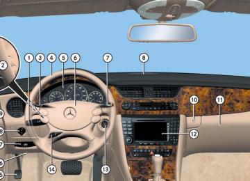
1 Washer and headlamp cleaning sys-
tem* For more information on refilling the reservoir, see “Washer system and headlamp cleaning system*” (컄 page 292). 2 Engine oil level
For more information on engine oil lev- el, see “Engine oil” (컄 page 287).
3 Brake fluid
For more information on brake fluid, see “Brake fluid” (컄 page 450).
4 Coolant level
For more information on the coolant level, see “Coolant level” (컄 page 290).
Operation At the gas station
Tire inflation pressure For more information, see “Checking tire inflation pressure” (컄 page 303).
285
Operation Engine compartment
Hood
Warning!
Do not pull the release lever while the vehi- cle is in motion. Otherwise the hood could be forced open by passing air flow.
This could cause the hood to come loose and injure you and/or others.
Opening
Warning!
If you see flames or smoke coming from the engine compartment, or if the coolant tem- perature gauge indicates that the engine is overheated, do not open the hood. Move away from vehicle and do not open the hood until the engine has cooled. If necessary, call the fire department.
286
Warning!
Warning!
The engine is equipped with a transistorized ignition system. Because of the high voltage it is dangerous to touch any components (ig- nition coils, spark plug sockets, diagnostic socket) of the ignition system 앫 with the engine running 앫 while starting the engine 앫 if ignition is “on” and the engine is
turned manually
You could be injured when the hood is open – even when the engine is turned off.
Parts of the engine can become very hot. To prevent burns, let the engine cool off com- pletely before touching any components on the vehicle. Comply with all relevant safety precautions.
Warning!
To help prevent personal injury, stay clear of moving parts when the hood is open and the engine is running.
The radiator fan may continue to run for approximately 30 seconds or even restart after the engine has been turned off. Stay clear of fan blades.
1 Release lever
왘 Pull release lever 1. The hood is unlocked.
! To avoid damage to the windshield wipers or hood, never open the hood if the wiper arms are folded forward away from the windshield.
1 Lever for opening the hood 왘 Push lever 1 on the hood upwards. 왘 Pull up on the hood and then release it.
The hood will be automatically held open at shoulder height by gas-filled struts.
Closing
Warning!
When closing the hood, use extreme caution not to catch hands or fingers. Be careful that you do not close the hood on anyone.
Make sure that the hood is securely en- gaged before driving off. Do not continue driving if the hood can no longer engage af- ter an accident, for example. The hood could otherwise come loose while the vehicle is in motion and endanger you and/or others.
왘 Let the hood drop from a height of
approximately 1 ft (30 cm). The hood will lock audibly.
왘 Check to make sure the hood is fully
closed. If you can raise the hood at a point above the headlamps, then it is not properly closed. Open it again and let it drop with somewhat greater force.
Operation Engine compartment
Engine oil
The amount of oil your engine needs will depend on a number of factors, including driving style. Higher oil consumption can occur when 앫 the vehicle is new 앫 the vehicle is driven frequently at
higher engine speeds
Engine oil consumption checks should only be made after the vehicle break-in period.
! Do not use any special lubricant additives, as these may damage the drive assemblies. Us- ing special additives not approved by Mercedes-Benz may cause damage not covered by the Mercedes-Benz Limited Warranty. More information on this subject is available at any Mercedes-Benz Center.
287
Operation Engine compartment
Checking engine oil level When checking the oil level 앫 the vehicle must be parked on level
ground
앫 with the engine at operating tempera- ture, the vehicle must have been sta- tionary for at least 5 minutes with the engine turned off
앫 with the engine not at operating tem- perature yet, the vehicle must have been stationary for at least 5 minutes with the engine turned off
288
왘 Pull out oil dipstick 1 again after
approximately 3 seconds to obtain ac- curate reading. The oil level is correct when it is be- tween lower (min) mark 3 and upper (max) mark 2 of oil dipstick 1.
i CLS 550 only: The filling quantity between the upper and lower marks on the oil dipstick is approximately 2.1 US qt. (2.0 l).
i CLS 63 AMG only: The filling quantity between the upper and lower marks on the oil dipstick is approximately 1.6 US qt. (1.5 l). 왘 If necessary, add engine oil. For adding engine oil, see “Adding engine oil” (컄 page 289). For more information on engine oil, see “Fuels, coolants, lubricants etc.” (컄 page 448).
1 Oil dipstick 2 Upper (max) mark 3 Lower (min) mark To check the engine oil level with the oil dipstick, do the following: 왘 Open the hood (컄 page 286). 왘 Pull out oil dipstick 1. 왘 Wipe oil dipstick 1 clean. 왘 Fully insert oil dipstick 1 into the
dipstick guide tube.
For more information on messages in the multifunction display concerning engine oil, see the “Practical hints” section (컄 page 379).
Adding engine oil
! Only use approved engine oils and oil filters required for vehicles with Maintenance System. For a listing of approved engine oils and oil fil- ters, refer to the Factory Approved Service Prod- ucts pamphlet (USA only) in your vehicle literature portfolio, or contact an authorized Mercedes-Benz Center. Using engine oils and oil filters of specification other than those expressly required for the Main- tenance System, or changing of oil and oil filter at change intervals longer than those called for by the Maintenance System will result in engine or emission control system damage not covered by the Mercedes-Benz Limited Warranty.
CLS 550
CLS 63 AMG 왘 Unscrew filler cap 1 from filler neck. 왘 Add engine oil as required. Be careful
not to overfill with oil.
Operation Engine compartment
Be careful not to spill any oil when adding. Avoid environmental damage caused by oil entering the ground or water.
! Excess oil must be siphoned or drained off. It could cause damage to the engine and emis- sion control system not covered by the Mercedes-Benz Limited Warranty. 왘 Screw filler cap 1 back on filler neck. For more information on engine oil, see the “Technical data” section (컄 page 448) and (컄 page 450).
Transmission fluid level
The transmission fluid level does not need to be checked. If you notice transmission fluid loss or gear shifting malfunctions, have an authorized Mercedes-Benz Center check the transmission.
289
Operation Engine compartment
Coolant level
The engine coolant is a mixture of water and anticorrosion/antifreeze. When checking the coolant level, 앫 the vehicle must be parked on level
ground
앫 the coolant temperature must be
below 158°F (70°C)
앫 Using a rag, slowly open the cap approx- imately 1/2 turn to relieve excess pres- sure. If opened immediately, scalding hot fluid and steam will be blown out under pressure.
앫 Do not spill antifreeze on hot engine
parts. Antifreeze contains ethylene gly- col which may burn if it comes into con- tact with hot engine parts.
Warning!
The coolant expansion tank is located on the driver’s side of the engine compart- ment.
In order to avoid potentially serious burns: 앫 Use extreme caution when opening the hood if there are any signs of steam or coolant leaking from the cooling system, or if the coolant temperature gauge indi- cates that the coolant is overheated.
앫 Do not remove pressure cap on coolant
reservoir if coolant temperature is above 158°F (70°C). Allow engine to cool down before removing cap. The coolant reservoir contains hot fluid and is under pressure.
290
1 Marking bar in the expansion tank 2 Cap 3 Coolant expansion tank
왘 Using a rag, turn cap 2 slowly approx- imately one half turn counterclockwise to release any excess pressure.
왘 Continue turning cap 2 counterclock-
wise and remove it. The coolant level is correct if the level: 앫 for cold coolant: reaches marking
bar 1 in expansion tank 3
앫 for warm coolant: is approximately
0.6 in (1.5 cm) higher 왘 Add coolant as required. 왘 Replace and tighten cap 2. For more information on coolant, see the “Technical data” section (컄 page 452).
Battery
Your vehicle’s battery is located in the trunk on the right hand side (컄 page 420). The battery should always be sufficiently charged in order to achieve their rated ser- vice life. Refer to Maintenance Booklet for battery maintenance intervals. If you use your vehicle mostly for short-dis- tance trips, you will need to have the bat- tery charge checked more frequently. When replacing the battery, always use batteries approved by Mercedes-Benz. If you do not intend to operate your vehicle for an extended period of time, consult an authorized Mercedes-Benz Center about steps you need to observe.
Warning!
Observe all safety instructions and precau- tions when handling automotive batteries.
Risk of explosion.
Fire, open flames and smoking are prohibited when handling batteries. Avoid creating sparks.
Battery acid is caustic. Do not allow it to come into contact with skin, eyes or clothing.
Wear suitable protective cloth- ing, especially gloves, apron and faceguard.
Operation Engine compartment
Wear eye protection.
Rinse any acid spills immediate- ly with clear water. Contact a physician if necessary.
Keep children away.
Follow the instructions in this Operator’s Manual.
Batteries contain materials that can harm the environment if disposed of improperly. Recycling of batteries is the preferred method of disposal. Many states require sellers of batteries to accept old batteries for recycling.
291
! Only use washer fluid which is suitable for plastic lenses. Improper washer fluid can dam- age the plastic lenses of the headlamps.
For more information, see “Windshield and headlamp washer fluid mixing ratio” (컄 page 455).
Operation Engine compartment
Washer system and headlamp cleaning system*
The washer reservoir is located in the en- gine compartment.
During all seasons, add MB Windshield Washer Concentrate “MB SummerFit” to water. Premix the washer fluid in a suitable container.
Warning!
Washer solvent/antifreeze is highly flamma- ble. Do not spill washer solvent/antifreeze on hot engine parts, because it may ignite and burn. You could be seriously burned.
왘 Use the tab to pull cap 1 upwards. 왘 Refill the reservoir with MB Windshield Washer Concentrate “MB SummerFit” and water (or commercially available premixed washer solvent/antifreeze, depending on ambient temperatures).
! Always use washer solvent/antifreeze where temperatures may fall below freezing point. Failure to do so could result in damage to the washer system/reservoir.
1 Cap for washer reservoir Fluid for the washer system and the head- lamp cleaning system is supplied from the washer reservoir. It has a capacity of ap- proximately 6.9 US qt (6.5 l).
292
왔 Tires and wheels Contact an authorized Mercedes-Benz Center for information on tested and rec- ommended rims and tires for summer and winter operation. They can also offer ad- vice concerning tire service and purchase.
Warning!
Replace rims or tires with the same designa- tion, manufacturer and type as shown on the original part. See an authorized Mercedes-Benz Center for further informa- tion. If incorrectly sized rims and tires are mounted: 앫 The wheel brakes or suspension compo-
nents can be damaged.
앫 The correct operating clearance of the wheels and the tires are no longer guar- anteed.
Warning!
Worn, old tires can cause accidents. If the tire tread is badly worn, or if the tires have sustained damage, replace them.
When replacing rims, only use genuine Mercedes-Benz wheel bolts specified for the particular rim type. Failure to do so can re- sult in the bolts loosening and possibly an accident.
Retreaded tires are not tested or recom- mended by Mercedes-Benz, since previous damage cannot always be recognized on re- treads. The operating safety of the vehicle cannot be assured when such tires are used.
Important guidelines
앫 Only use sets of tires and rims of the
same type and make.
앫 Tires must be of the correct size for the
rim.
Operation Tires and wheels
앫 Break in new tires for approximately
60 miles (100 km) at moderate speeds.
앫 Regularly check the tires and rims for
damage. Dented or bent rims can cause tire inflation pressure loss and damage to the tire beads.
앫 If vehicle is heavily loaded, check tire
inflation pressure and correct as re- quired.
앫 Do not allow your tires to wear down too far. Adhesion properties on wet roads are sharply reduced at tread depths of less than 1/8 in (3 mm).
앫 The wheels on the front and rear axles
are different. For this reason, pay at- tention to the markings on the inside of the wheel rims. Wheels marked “REAR AXLE ONLY” on the inside of the rim may only be fitted on the rear axle. 앫 When replacing individual tires, you should mount new tires on the front wheels first (on vehicles with same-sized wheels all around).
293
Operation Tires and wheels
Tire care and maintenance
앫 cord or fabric showing through the
Warning!
tire’s rubber
앫 bumps, bulges, cuts, cracks or splits in
the tread or side of the tire
Regularly check the tires for damage. Dam- aged tires can cause tire inflation pressure loss. As a result, you could lose control of your vehicle.
Worn, old tires can cause accidents. If the tire tread is badly worn, or if the tires have sustained damage, replace them.
Replace the tire if you find any of the above conditions. Make sure you also inspect the spare tire periodically for condition and inflation. Spare tires will age and become worn over time even if never used, and thus should be inspected and replaced when necessary.
Regularly check your tire inflation pressure at least once a month. For more informa- tion on checking tire inflation pressure see “Recommended tire inflation pressure” (컄 page 301).
Tire inspection Every time you check your tire inflation pressure, you should also inspect your tires for the following: 앫 excessive treadwear (컄 page 294)
Life of tire The service life of a tire is dependent upon varying factors including but not limited to: 앫 Driving style 앫 Tire inflation pressure 앫 Distance driven
Warning!
Tires and spare tire should be replaced after 6 years, regardless of the remaining tread.
Tread depth Do not allow your tires to wear down too far. Adhesion properties on wet roads are sharply reduced at tread depths of less than 1⁄8 in (3 mm). Tread wear indicators (TWI) are required by law. These indicators are located in six places on the tread circumference and become visible at a tread depth of approx- imately 1/16 in (1.6 mm), at which point the tire is considered worn and should be re- placed. Recommended minimum tire tread depth: 앫 Summer tires 1/8 in (3 mm) 앫 Winter tires 1/6 in (4 mm)
Warning!
Although the applicable federal motor safety laws consider a tire to be worn when the treadwear indicators (TWI) become visible at approximately 1/16 in (1.6 mm), we recom- mend that you do not allow your tires
294
Operation Tires and wheels
Storing tires
Direction of rotation
! Keep unmounted tires in a cool, dry place with as little exposure to light as possible. Pro- tect tires from contact with oil, grease and gaso- line.
Cleaning tires
! Never use a round nozzle to power wash tires. The intense jet of water can result in damage to the tire. Always replace a damaged tire.
Unidirectional tires offer added advan- tages, such as better hydroplaning perfor- mance. To benefit, however, you must make sure the tires rotate in the direction specified. An arrow on the sidewall indicates the intended direction of rotation (spinning) of the tire.
i Spare wheels may be mounted against the direction of rotation (spinning) even with a unidi- rectional tire for temporary use only until the reg- ular drive wheel has been repaired or replaced. Always observe and follow applicable temporary use restrictions and speed limitations indicated on the spare wheel.
to wear down to that level. As tread depth approaches 1/8 in (3 mm), the adhesion properties on a wet road are sharply reduced.
Depending upon the weather and/or road surface (conditions), the tire traction varies widely.
1 TWI (Tread Wear Indicator) The treadwear indicator appears as a solid band across the tread.
295
Operation Tires and wheels
Loading the vehicle
2) The certification label, also found on
Two labels on your vehicle show how much weight it may properly carry. 1) The Tire and Loading Information
placard can be found on the driver’s door B-pillar. This placard tells you im- portant information about the number of people that can be in the vehicle and the total weight that can be carried in the vehicle. It also contains information on the proper size and recommended tire inflation pressures for the original equipment tires on your vehicle.
the driver’s door B-pillar tells you about the gross weight capacity of your vehi- cle, called the Gross Vehicle Weight Rating (GVWR). The GVWR includes the weight of the vehicle, all occupants, fuel and cargo. The certification label also tells you about the front and rear axle weight capacity, called the Gross Axle Weight Rating (GAWR). The GAWR is the total allowable weight that can be carried by a single axle (front or rear). Never exceed the GVWR or GAWR for either the front axle or rear axle.
Following is a discussion on how to work with the information contained on the Tire and Loading Information placard with re- gards to loading your vehicle.
Tire and Loading Information
Warning!
Do not overload the tires by exceeding the specified total load limit as indicated on the Tire and Loading Information placard on the driver’s door B-pillar. Overloading the tires can overheat them, possibly causing a blowout. Overloading the tires can also result in handling or steering problems, or brake failure.
1 Driver’s door B-pillar
296
왘 Locate the statement “The combined weight of occupants and cargo should never exceed XXX kilograms or XXX lbs.” on the Tire and Loading Infor- mation placard. The combined weight of all occupants, cargo/luggage and trailer tongue load (if applicable) should never exceed the weight referenced in that statement.
Seating capacity The seating capacity gives you important information on the number of occupants that can be in the vehicle. Observe front and rear seating capacity. The Tire and Loading Information placard showing the seating capacity is located on the driver’s door B-pillar (컄 page 296).
Tire and Loading Information placard
i Data shown on Tire and Loading Information placard example are for illustration purposes only. Seating data are specific to each vehicle and may vary from data shown in the illustration below. Refer to Tire and Loading Information placard on vehicle for actual data specific to your vehicle.
1 Load limit information on the Tire and
Loading Information placard
The Tire and Loading Information placard showing the load limit information is locat- ed on the driver’s door B-pillar (컄 page 296).
Operation Tires and wheels
i Data shown on Tire and Loading Information placard example are for illustration purposes only. Seating data are specific to each vehicle and may vary from data shown in the illustration below. Refer to Tire and Loading Information placard on vehicle for actual data specific to your vehicle.
1 Seating capacity information on the Tire and Loading Information placard
297
Step 4
왘 The resulting figure equals the avail-Step 6 (if applicable) 왘 If your vehicle will be towing a trailer,
able amount of cargo and luggage load capacity. For example, if the “XXX” amount equals 1400 lbs. and there will be five 150 lbs. passengers in your vehicle, the amount of available cargo and luggage load capacity is 650 lbs. (1400-750 (5 x150) = 650 lbs.)
Step 5
왘 Determine the combined weight ofluggage and cargo being loaded on the vehicle. That weight may not safely exceed the available cargo and luggage load capacity calculated in step 4.
load from your trailer will be trans- ferred to your vehicle. Consult this manual to determine how this reduces the available cargo and luggage load capacity of your vehicle (컄 page 300).
The following table shows examples on how to calculate total and cargo load capacities with varying seating configura- tions and number and size of occupants. The following examples use a load limit of 1500 lbs. This is for illustration purposes only. Make sure you are using the actual load limit for your vehicle stated on the vehicle’s Tire and Loading Informa- tion placard (컄 page 297).
Operation Tires and wheels
Steps for determining correct load limit The following steps have been developed as required of all manufacturers under Title 49, Code of U.S. Federal Regulations, Part 575 pursuant to the “National Traffic and Motor Vehicle Safety Act of 1966”. Step 1
왘 Locate the statement “The combined weight of occupants and cargo should never exceed XXX kg or XXX lbs.” on your vehicle’s Tire and Loading Infor- mation placard.Step 2
왘 Determine the combined weight of thedriver and passengers that will be riding in your vehicle.
Step 3
왘 Subtract the combined weight of thedriver and passengers from XXX kilograms or XXX lbs.
298
Operation Tires and wheels
Number of occupants (driver and passengers)
Seating configura- tion
Occupants weight
Combined weight of all occupants
Available cargo/luggage and trailer tongue weight (total load limit from placard minus combined weight of all occupants)
front: 2
rear: 2
front: 1
rear: 2front:1
Occupant 1: 150 lbs Occupant 2: 180 lbs Occupant 3: 160 lbs Occupant 4: 140 lbs Occupant 1: 200 lbs Occupant 2: 190 lbs Occupant 3: 150 lbs Occupant 1: 150 lbs
630 lbs
1500 lbs - 630 lbs = 870 lbs
540 lbs
1500 lbs - 540 lbs = 960 lbs
150 lbs
1500 lbs - 150 lbs = 1350 lbs
Example Combined
weight limit of occu- pants and cargo from Tire and Loading In- formation placard 1500
1500
1500
The higher the weight of all occupants, the less cargo and luggage load capacity is available. For more information, see “Trailer tongue load” (컄 page 300).
299
Operation Tires and wheels
Certification label Even after careful determination of the combined weight of all occupants, cargo and the trailer tongue load (if applicable) (컄 page 300) as to not exceed the permis- sible load limit, you must make sure that your vehicle never exceeds the Gross Vehi- cle Weight Rating (GVWR) and the Gross Axle Weight Rating (GAWR) for either the front or rear axle. You can obtain the GVWR and GAWR from the certification label. The certification label can be found on the driver’s door B-pillar, see “Technical data” (컄 page 434).
Gross Vehicle Weight Rating (GVWR): The total weight of the vehicle, all occupants, all cargo, and the trailer tongue load (컄 page 300) must never exceed the GVWR. Gross Axle Weight Rating (GAWR): The to- tal allowable weight that can be carried by a single axle (front or rear). To assure that your vehicle does not ex- ceed the maximum permissible weight limits (GVWR and GAWR for front and rear axle), have the loaded vehicle (including driver, passengers and all cargo and, if applicable, trailer fully loaded) weighed on a suitable commercial scale.
Trailer tongue load The tongue load of any trailer is an impor- tant weight to measure because it affects the load you can carry in your vehicle. If a trailer is towed, the tongue load must be added to the weight of all occupants riding and any cargo you are carrying in the vehicle. The tongue load typically is be- tween 10% and 15% of the trailer weight and everything loaded in it. Your Mercedes-Benz has been designed primarily to carry passengers and their cargo. Mercedes-Benz does not recom- mend trailer towing with your vehicle.
300
Recommended tire inflation pressure
Warning!
Follow recommended tire inflation pressures.
Do not underinflate tires. Underinflated tires wear excessively and/or unevenly, adversely affect handling and fuel economy, and are more likely to fail from being over- heated.
Do not overinflate tires. Overinflated tires can adversely affect handling and ride comfort, wear unevenly, increase stopping distance, and result in sudden deflation (blowout) because they are more likely to become punctured or damaged by road debris, potholes etc.
Do not overload the tires by exceeding the specified load limit as indicated on the Tire and Loading Information placard on the driv- er’s door B-pillar. Overloading the tires can overheat them, possibly causing a blowout. Overloading the tires can also result in han- dling or steering problems, or brake failure.
Your vehicle is equipped with the Tire and Loading Information placard located on the driver’s door B-pillar (컄 page 296). The tire inflation pressure should be checked regularly and should only be ad- justed on cold tires. The tires can be con- sidered cold if the vehicle has been parked for at least 3 hours or driven less than 1 mile (1.6 km). Follow recommended cold tire inflation pressures listed on Tire and Loading Infor- mation placard on the driver’s door B-pil- lar. Keeping the tires properly inflated provides the best handling, tread life and riding comfort.
Operation Tires and wheels
In addition to the Tire and Loading Informa- tion placard on the driver’s door B-pillar, also consult the tire inflation pressure la- bel (if available) on the fuel filler flap for any additional information pertaining to special driving situations. For more infor- mation, see “Important notes on tire infla- tion pressure” (컄 page 302).
i Data shown on Tire and Loading Information placard example are for illustration purposes only. Tire data are specific to each vehicle and may vary from data shown in the illustration be- low. Refer to Tire and Loading Information plac- ard on vehicle for actual data specific to your vehicle.
301
Operation Tires and wheels
1 Tire and Loading Information placard with recommended cold tire inflation pressures
The Tire and Loading Information placard lists the recommended cold tire inflation pressures for maximum loaded vehicle weight. The tire inflation pressures listed apply to the tires installed as original equipment.
302
Important notes on tire inflation pressure
Warning!
If the tire inflation pressure drops repeatedly: 앫 Check the tires for punctures from
foreign objects.
앫 Check to see whether air is leaking from
the valves or from around the rim.
Tire temperature and tire inflation pressure are also increased while driving, depending on the driving speed and the tire load. If you will be driving your vehicle at high speeds of 100 mph (160 km/h) or higher, where it is legal and conditions allow, con- sult the tire inflation pressure label on the inside of the fuel filler flap (if available) on how to adjust the cold tire inflation pres- sure. If you do not adjust the tire inflation pressure, excessive heat can build up and result in sudden tire failure.
If your vehicle is not equipped with the tire inflation pressure label on the inside of the fuel filler flap, contact an authorized Mercedes-Benz Center for proper tire infla- tion pressure.
i Driving comfort may be reduced when the tire inflation pressure is adjusted to the value for speeds above 100 mph (160 km/h) as specified on the tire inflation pressure label located on the inside of the fuel filler flap.
Be sure to readjust the tire inflation pressure for normal driving speeds. You should wait until the tires are cold before adjusting the tire inflation pressure. Some vehicles may have supplemental tire inflation pressure information for vehicle loads less than the maximum loaded vehi- cle condition. If such information is provid- ed, it can be found on the tire inflation pressure label located on the inside of the fuel filler flap.
Tire inflation pressure changes by approxi- mately 1.5 psi (0.1 bar) per 18°F (10°C) of air temperature change. Keep this in mind when checking tire inflation pressure where the temperature is different from the outside temperature.
Checking tire inflation pressure
Regularly check your tire inflation pressure at least once a month. Check and adjust the tire inflation pressure when the tires are cold. The tires can be considered cold if the vehicle has been parked for at least 3 hours or driven less than 1 mile (1.6 km). If you check the tire inflation pressure when the tires are warm (the vehicle has been driven for several miles or sitting less than 3 hours), the reading will be approximately 4 psi (0.3 bar) higher than the cold reading. This is normal. Do not let air out to match the specified cold tire inflation pressure. Otherwise, the tire will be underinflated.
Operation Tires and wheels
Warning!
Follow recommended tire inflation pressures.
Do not underinflate tires. Underinflated tires wear excessively and/or unevenly, adversely affect handling and fuel economy, and are more likely to fail from being over- heated.
Do not overinflate tires. Overinflated tires can adversely affect handling and ride comfort, wear unevenly, increase stopping distance, and result in sudden deflation (blowout) because they are more likely to become punctured or damaged by road debris, potholes etc.
Do not overload the tires by exceeding the specified total load limit as indicated on the Tire and Loading Information placard on the driver’s door B-pillar. Overloading the tires can overheat them, possibly causing a blow- out. Overloading the tires can also result in handling or steering problems, or brake fail- ure.
303
Operation Tires and wheels
Checking tire inflation pressure manually Follow the steps below to achieve correct tire inflation pressure: 왘 Remove the cap from the valve on one
tire.
왘 Firmly press a tire gauge onto the
valve.
왘 Read tire inflation pressure on tire
gauge and check against the recom- mended tire inflation pressure on the Tire and Loading Information placard on the driver’s door B-pillar (컄 page 296) or, if available, the inside of the fuel filler flap. If necessary, add air to achieve the recommended tire inflation pressure.
i If you have overfilled the tire, release tire in- flation pressure by pushing the metal stem of the valve with e.g. a tip of a pen. Then recheck the tire inflation pressure with the tire gauge. 왘 Install the valve cap. 왘 Repeat this procedure for each tire.
304
Run Flat Indicator (Canada only) While the vehicle is being driven, the Run Flat Indicator monitors the set tire inflation pressures by evaluating each wheel’s rota- tional speed. This allows the system to de- tect a significant loss of pressure in a tire. If a wheel’s rotational speed changes due to falling tire inflation pressure, you will see a corresponding warning message in the multifunction display. The Run Flat Indicator may function in a restricted manner or with a delay 앫 if snow chains are mounted to the
vehicle
앫 in winter road conditions prevail in
presence of ice and snow
앫 if you are driving on a loose surface
(e.g. sand or gravel)
앫 if you are driving in a very sporty man- ner (involving rapid acceleration or high speeds in curves)
Warning!
When the multifunction display shows the message Tire Pressure Check Tires, one or more of your tires is significantly un- derinflated. You should stop and check your tires as soon as possible, and inflate them to the proper tire inflation pressure as indicat- ed on the vehicle’s Tire and Loading Infor- mation placard or, if available, on the tire inflation pressure label. Driving on a signifi- cantly underinflated tire causes the tire to overheat and can lead to tire failure. Under- inflation also reduces fuel efficiency and tire tread life, and may affect the vehicle’s han- dling and stopping ability. Each tire, includ- ing the spare, should be checked monthly when cold and set to the recommended tire inflation pressure as specified on the Tire and Loading Information placard on the driv- er’s door B-pillar (컄 page 296) or, if avail- able, on the tire inflation pressure label located on the inside of the fuel filler flap.
Warning!
The Run Flat Indicator does not provide a warning for wrongly selected tire inflation pressures. Always adjust tire inflation pres- sure according to the Tire and Loading Infor- mation placard on the driver’s door B-pillar (컄 page 296) or, if available, on the tire in- flation pressure label located on the inside of the fuel filler flap.
The Run Flat Indicator does not replace reg- ular checks of the tire inflation pressures since a gradual pressure loss in more than one tire cannot be detected by the Run Flat Indicator.
The Run Flat Indicator is not able to issue a warning due to a sudden dramatic loss of tire inflation pressure (e.g. tire blowout caused by a foreign object). In this case bring the vehicle to a halt by carefully apply- ing the brakes and avoiding abrupt steering maneuvers.
Restarting the Run Flat Indicator The tire inflation pressure monitor must be restarted in the following situations: 앫 If you have changed the tire inflation
pressure
앫 If you have replaced the wheels or tires 앫 If you have installed new wheels or
tires
왘 Using the Tire and Loading Information placard on the driver’s door B-pillar or, if available, the tire inflation pressure label on the inside of the fuel filler flap, make sure the tire inflation pressure of all four tires is correct.
Warning!
The Run Flat Indicator can only warn you in a reliable manner if you have set the correct tire inflation pressures for each tire.
If an incorrect tire inflation pressure was set, the system will monitor the pressure ac- cording to the incorrect value.
Operation Tires and wheels
왘 Switch on the ignition (컄 page 38).
Make sure the standard display menu appears in the multifunction display (컄 page 139).
왘 Press button k or j repeatedly until the following message appears in the multifunction display: Run Flat Indicator Active Menu: R-Button
왘 Press the reset button (컄 page 27).
The following message will appear in the multifunction display: Restart Run Flat Indicator? Cancel Yes
If you wish to confirm activation: 왘 Press button æ.
The following message will appear in the multifunction display: Run Flat Indicator Restarted
컄컄
305
Checking tire inflation pressure elec- tronically with the Tire Pressure Moni- toring System (TPMS), (USA only)
i The Tire Pressure Monitoring System (TPMS) is equipped with a combination low tire pressure/TPMS malfunction telltale in the in- strument cluster (컄 page 27). Depending on how the telltale illuminates, it indicates a low tire pressure condition or a malfunction in the TPMS system itself: 앫 If the telltale illuminates continuously, one or more of your tires is significantly underin- flated. There is no malfunction in the TPMS.
앫 If the telltale flashes for 60 seconds and then stays illuminated, the TPMS system itself is not operating properly.
i This device complies with Part 15 of the FCC Rules. Operation is subject to the following two conditions: (1) This device may not cause harmful interfer-
ence, and
(2) this device must accept any interference re-
ceived, including interference that may cause undesired operation.
Any unauthorized modification to this device could void the user’s authority to operate the equipment.
The TPMS only functions on wheels that are equipped with the proper electronic sensors. It monitors the tire inflation pres- sure, as selected by the driver, in all four tires. A warning is issued to alert you to a decrease in pressure in one or more of the tires.
Operation Tires and wheels
컄컄
After a certain “learning phase”, the Run Flat Indicator checks the set pressure val- ues for all four tires. If you wish to cancel activation: 왘 Press button ç. or 왘 Wait until the message
Restart Run Flat Indicator? Cancel Yes disappears.
306
Warning!
Warning!
the tire to overheat and can lead to tire fail- ure.
Operation Tires and wheels
The TPMS does not indicate a warning for wrongly selected inflation pressures. Always adjust tire inflation pressure according to the Tire and Loading Information placard on the driver’s door B-pillar or, if available, the supplemental tire inflation pressure infor- mation on the inside of the fuel filler flap.
The TPMS is not able to issue a warning due to a sudden dramatic loss of pressure (e.g. tire blowout caused by a foreign object). In this case bring the vehicle to a halt by care- fully applying the brakes and avoiding abrupt steering maneuvers.
Each tire, including the spare (if provided), should be checked monthly when cold and inflated to the inflation pressure recom- mended by the vehicle manufacturer on the Tire and Loading Information placard on the driver’s door B-pillar or, if available, the tire inflation pressure label on the fuel filler flap. If your vehicle has tires of a different size than the size indicated on the Tire and Load- ing Information placard or, if available, the tire inflation pressure label, you should de- termine the proper tire inflation pressure for those tires.
As an added safety feature, your vehicle has been equipped with a tire pressure monitor- ing system (TPMS) that illuminates a low tire pressure telltale when one or more of your tires is significantly underinflated. Accord- ingly, when the low tire pressure telltale illu- minates, you should stop and check your tires as soon as possible, and inflate them to the proper pressure. Driving on a significant- ly underinflated tire causes
Underinflation also reduces fuel efficiency and tire tread life, and may affect the vehi- cle’s handling and stopping ability. Please note that the TPMS is not a substitute for proper tire maintenance, and it is the driver’s responsibility to maintain correct tire pressure, even if underinflation has not reached the level to trigger illumination of the TPMS low tire pressure telltale.
Your vehicle has also been equipped with a TPMS malfunction indicator to indicate when the system is not operating properly. The TPMS malfunction indicator is com- bined with the low tire pressure telltale. When the system detects a malfunction, the telltale will flash for approximately 1 minute and then remain continuously illuminated. This sequence will continue upon subse- quent vehicle start-ups as long as the mal- function exists. When the malfunction indicator is illuminated, the system may not be able to detect or signal low tire pressure as intended.
컄컄
307
Operation Tires and wheels
컄컄
TPMS malfunctions may occur for a variety of reasons, including the installation of in- compatible replacement or alternate tires or wheels on the vehicle that prevent the TPMS from functioning properly. Always check the TPMS malfunction telltale after replacing one or more tires or wheels on your vehicle to ensure that the replacement or alternate tires and wheels allow the TPMS to continue to function properly.
i If a condition causing the TPMS to malfunc- tion develops, it may take up to 10 minutes for the system to signal a malfunction using the TPMS telltale flashing and illumination se- quence. The telltale extinguishes after a few minutes driv- ing if the malfunction has been corrected.
i Operating radio transmission equipment (e.g. wireless headsets, two-way radios) in or near the vehicle could cause the TPMS to mal- function.
308
Tire inflation warnings If the system detects a significant loss of tire inflation pressure in one or more than one tire, a message appears in the multi- function display.
Example illustration In addition, a warning signal sounds.
Restarting the TPMS
Warning!
It is the driver’s responsibility to calibrate the TPMS on the recommended cold infla- tion pressure. Underinflated tires affect the ability to steer or brake the vehicle. You might lose control over the vehicle.
The TPMS must be restarted when you have adjusted the tire inflation pressure to a new level (e.g. because of different load or driving conditions). The TPMS is then recalibrated to the current tire inflation pressures. 왘 Using the Tire and Loading Information
placard on the driver’s door B-pillar (컄 page 296) or, if available, the sup- plemental tire inflation pressure information on the inside of the fuel fill- er flap (컄 page 283), make sure the tire inflation pressure of all four tires is cor- rect.
Operation Tires and wheels
i Restart the TPMS after adjusting the tire in- flation pressure to the inflation pressure recom- mended for the vehicle operating condition. Tire pressure should only be adjusted on cold tires. Observe the recommended tire inflation pres- sure on the Tire and Loading Information placard on the driver’s door B-pillar (컄 page 296). Some vehicles may have supplemental tire inflation pressure information for driving at high speeds (컄 page 302) or for vehicle loads less than the maximum loaded vehicle condition (컄 page 302). If such information is provided, it can be found on the inside of the fuel filler flap (컄 page 283). 왘 Switch on the ignition (컄 page 38). 왘 Press button è or ÿ on the mul-
tifunction steering wheel repeatedly until the standard display menu ap- pears in the multifunction display (컄 page 139).
왘 Press the j or k button repeat- edly until you see the flowing message: Tire Pressure Monitor Active Menu: R-Button
왘 Press the reset button (컄 page 27).
The following message will appear in the multifunction display: Restart tire pressure monitor? Cancel Yes
왘 Press the æ button.
The following message will appear in the multifunction display: Tire Pressure Monitor Restarted After driving a few minutes the current tire inflation pressure values are ac- cepted as reference pressures and then monitored.
If you wish to cancel activation: 왘 Press the ç button.
Checking tire inflation pressure elec- tronically with the Advanced Tire Pres- sure Monitoring System* (Advanced TPMS*), (Canada only)
i This device complies with RSS-210 of Indus- try Canada. Operation is subject to the following two conditions: (1) This device may not cause interference, and (2) this device must accept any interference re-
ceived, including interference that may cause undesired operation of the device. Any unauthorized modification to this device could void the user’s authority to operate the equipment.
The TPMS only functions on wheels that are equipped with the proper electronic sensors. It monitors the tire inflation pres- sure, as selected by the driver, in all four tires. A warning is issued to alert you to a decrease in pressure in one or more of the tires.
309
Operation Tires and wheels
Tire pressure inquiries are made using the multifunction display. The present inflation pressures are displayed only after a few minutes travel time.
i Possible differences between the readings of a tire pressure gauge of an air hose, e.g. gas station equipment, and the vehicle’s control sys- tem can occur. Usually the readings issued by the control system are more precise. 왘 Switch on the ignition (컄 page 38). 왘 Press the j or k button until
the current inflation pressures for each tire appear in the multifunction display.
i When the vehicle has been parked for longer than 20 minutes, the message Tire pressure is only displayed after driving for a few minutes. appears in the multifunction dis- play.
310
Warning!
It is the driver’s responsibility to calibrate the TPMS on the recommended cold infla- tion pressure. Underinflated tires affect the ability to steer or brake the vehicle. You might lose control over the vehicle.
i With a spare wheel without wheel sensor mounted, the system may still indicate the tire inflation pressure of the removed wheel for some minutes. If this happens, keep in mind that the indicated value where the spare wheel is mount- ed does not reflect the actual spare tire inflation pressure.
Warning!
The TPMS does not indicate a warning for wrongly selected inflation pressures. Always adjust tire inflation pressure according to the Tire and Loading Information placard on the driver’s door B-pillar or, if available, the supplemental tire inflation pressure infor- mation on the inside of the fuel filler flap.
The TPMS is not able to issue a warning due to a sudden dramatic loss of pressure (e.g. tire blowout caused by a foreign object). In this case bring the vehicle to a halt by care- fully applying the brakes and avoiding abrupt steering maneuvers.
Warning!
Each tire, including the spare (if provided), should be checked monthly when cold and inflated to the inflation pressure recom- mended by the vehicle manufacturer on the Tire and Loading Information placard on the driver’s door B-pillar or, if available, the tire inflation pressure label on the fuel filler flap. (If your vehicle has tires of a different size than the size indicated on the Tire and Load- ing Information placard or, if available, the tire inflation pressure label, you should de- termine the proper tire inflation pressure for those tires).
As an added safety feature, your vehicle has been equipped with a tire pressure monitor- ing system (TPMS) that illuminates a low tire pressure telltale when one or more of your tires is significantly underinflated. Accord- ingly, when the low tire pressure telltale illu- minates, you should stop and check your tires as soon as possible, and inflate them to the proper pressure. Driving on a significant- ly underinflated tire causes the tire to over- heat and can lead to tire failure.
Underinflation also reduces fuel efficiency and tire tread life, and may affect the vehi- cle’s handling and stopping ability. Please note that the TPMS is not a substitute for proper tire maintenance, and it is the driv- er’s responsibility to maintain correct tire pressure, even if underinflation has not reached the level to trigger illumination of the TPMS low tire pressure telltale.
i Operating radio transmission equipment (e.g. wireless headsets, two-way radios) in or near the vehicle could cause the TPMS to mal- function.
Tire inflation pressure warnings If the system detects a significant loss of tire inflation pressure in one or more than one tire, a message appears in the multi- function display.
Example illustration The respective tire is indicated by a red rectangle. In addition, a warning signal sounds.
Operation Tires and wheels
Restarting Advanced TPMS* The TPMS usually recognizes new refer- ence values automatically, for example when you have 앫 adjusted the tire inflation pressure 앫 changed wheels or tires 앫 mounted new wheels or tires
Warning!
It is the driver’s responsibility to calibrate the TPMS on the recommended cold infla- tion pressure. Underinflated tires affect the ability to steer or brake the vehicle. You might lose control over the vehicle.
311
Operation Tires and wheels
If you want to set new reference values manually: 왘 Using the Tire and Loading Information placard on the driver’s door B-pillar or, if available, the supplemental tire infla- tion pressure information on the inside of the fuel filler flap, make sure the tire inflation pressure of all four tires is cor- rect.
i Restart the TPMS after adjusting the tire in- flation pressure to the inflation pressure recom- mended for the vehicle operating condition. Tire pressure should only be adjusted on cold tires. Observe the recommended tire inflation pres- sure on the Tire and Loading Information placard on the driver’s door B-pillar (컄 page 296). Some vehicles may have supplemental tire inflation pressure information for driving at high speeds (컄 page 302) or for vehicle loads less than the maximum loaded vehicle condition. If such infor- mation is provided, it can be found on the inside of the fuel filler flap.
312
왘 Press button è or ÿ on the mul-
왘 Press the æ button.
The following message will appear in the multifunction display: Tire Pressure Monitor Restarted After driving a few minutes the system verifies that the current tire inflation pressures are within the system’s specified range. Afterwards the current tire inflation pressures are accepted as reference pressures and then moni- tored.
If you wish to cancel activation: 왘 Press the ç button.
tifunction steering wheel repeatedly until the standard display menu ap- pears in the multifunction display (컄 page 145).
왘 Press the j or k button repeat- edly until you see the current inflation pressures for each tire appear in the multifunction display or the following message appears in the multifunction display: Tire pressure is only displayed after driving for a few minutes
왘 Press the reset button (컄 page 27).
The following message will appear in the multifunction display: Restart tire pressure monitor? Cancel Yes
Potential problems associated with underinflated and overinflated tires
Underinflated tires Underinflated tires can: 앫 cause excessive and uneven tire wear 앫 adversely affect fuel economy 앫 lead to tire failure from being
overheated
앫 adversely affect handling
characteristics
Warning!
Follow recommended tire inflation pressures.
Do not underinflate tires. Underinflated tires wear excessively and/or unevenly, adversely affect handling and fuel economy, and are more likely to fail from being overheated.
Overinflated tires Overinflated tires can: 앫 adversely affect handling
characteristics
앫 cause uneven tire wear 앫 be more prone to damage from road
hazards
앫 adversely affect ride comfort 앫 increase stopping distance
Warning!
Follow recommended tire inflation pressures.
Do not overinflate tires. Overinflated tires can adversely affect handling and ride comfort, wear unevenly, increase stopping distance, and result in sudden deflation (blowout) because they are more likely to become punctured or damaged by road debris, potholes etc.
Operation Tires and wheels
MOExtended system*
The MOExtended system allows you to continue driving your vehicle even if there is a total loss of pressure in one or more tires. You may only use the MOExtended system in conjunction with the Run Flat Indicator (Canada only) (컄 page 304) or the TPMS (USA only) (컄 page 306) or the Advanced TPMS* (Canada only) (컄 page 309). For information on driving in case of pres- sure loss in one or more tires (emergency mode), see the “Practical hints” section (컄 page 419).
313
Operation Tires and wheels
Tire labeling
Besides tire name (sales designation) and manufacturer name, a number of markings can be found on a tire. Following are some explanations for the markings on your vehicle’s tires:
314
1 Uniform Tire Quality Grading Standards
(컄 page 321)
Tire size designation, load and speed rating
2 DOT, Tire Identification Number (TIN)
(컄 page 318)
3 Maximum tire load (컄 page 320) 4 Maximum tire inflation pressure
(컄 page 320) 5 Manufacturer 6 Tire ply material (컄 page 323) 7 Tire size designation, load and speed
rating (컄 page 314)
8 Load identification (컄 page 318) 9 Tire name
i For illustration purposes only. Actual data on tires are specific to each vehicle and may vary from data shown in above illustration. For more information, see “Rims and tires” (컄 page 438).
1 Tire width 2 Aspect ratio in % 3 Radial tire code 4 Rim diameter 5 Tire load rating 6 Tire speed rating
i For illustration purposes only. Actual data on tires are specific to each vehicle and may vary from data shown in above illustration.
Tire width The tire width 1 (컄 page 314) indicates the nominal tire width in mm.
Aspect ratio The aspect ratio 2 (컄 page 314) is the dimensional relationship between tire section height and section width and is expressed in percentage. The aspect ratio is arrived at by dividing section height by section width.
General: Depending on the design standards used, the tire size molded into the sidewall may have no letter or a letter preceding the tire size designation. No letter preceding the size designation (as illustrated above): Passenger car tire based on European design standards. Letter “P” preceding the size designation: Passenger car tire based on U.S. design standards. Letter “LT” preceding the size designation: Light Truck tire based on U.S. design standards. Letter “T” preceding the size designation: Temporary spare tires which are high pressure compact spares designed for temporary emergency use only.
Operation Tires and wheels
Tire code The tire code 3 (컄 page 314) indicates the tire construction type. The “R” stands for radial tire type. Letter “D” means diag- onal or bias ply construction; letter “B” means belted-bias ply construction. At the tire manufacturer’s option, any tire with a speed capability above 149 mph (240 km/h) can include a “ZR” in the size designation (for example: 245/40 ZR 18). For additional information, see “Tire speed rating” (컄 page 316).
Rim diameter The rim diameter 4 (컄 page 314) is the diameter of the bead seat, not the diameter of the rim edge. Rim diameter is indicated in inches (in).
315
Operation Tires and wheels
Tire load rating The tire load rating 5 (컄 page 314) is a numerical code associated with the maximum load a tire can support. For example, a load rating of 91 corre- sponds to a maximum load of 1356 lbs (615 kg) the tire is designed to support. See also “Maximum tire load” (컄 page 320) where the maximum load as- sociated with the load index is indicated in kilograms and lbs.
Warning!
The tire load rating must always be at least half of the GAWR (컄 page 324) of your vehicle. Otherwise, tire failure may be the result which may cause an accident and/or serious personal injury to you or others.
Always replace rims and tires with the same designation, manufacturer and type as shown on the original part.
316
Warning!
Do not overload the tires by exceeding the specified total load limit as indicated on the Tire and Loading Information placard locat- ed on the driver’s door B-pillar. Overloading the tires can overheat them, possibly caus- ing a blowout. Overloading the tires can also result in handling or steering problems, or brake failure.
For additional information on tire load rating, see “Load identification” (컄 page 318). i Tire load rating 5 (컄 page 314) and tire speed rating 6 (컄 page 314) are also referred to as “service description”.
Tire speed rating The tire speed rating 6 (컄 page 314) indicates the approved maximum speed for the tire.
Warning!
Even when permitted by law, never operate a vehicle at speeds greater than the maximum speed rating of the tires.
Exceeding the maximum speed for which tires are rated can lead to sudden tire failure, causing loss of vehicle control and possibly resulting in an accident and/or personal injury and possible death, for you and for others.
i Tire load rating 5 (컄 page 314) and tire speed rating 6 (컄 page 314) are also referred to as “service description”.
Summer tires
Index (Y) ZR
Speed rating up to 100 mph (160 km/h) up to 106 mph (170 km/h) up to 112 mph (180 km/h) up to 118 mph (190 km/h) up to 130 mph (210 km/h) up to 149 mph (240 km/h) up to 168 mph (270 km/h) up to 186 mph (300 km/h) above 186 mph (300 km/h) above 149 mph (240 km/h)
앫 At the tire manufacturer’s option, any
tire with a speed capability above 149 mph (240 km/h) can include a “ZR” in the size designation (for exam- ple: 245/40 ZR18). To determine the maximum speed capability of the tire, the service description for the tire must be referred to. The service description
Operation Tires and wheels
is comprised of the tire load rating 5 (컄 page 314) and the tire speed rating 6 (컄 page 314). If your tire includes “ZR” in the size designation and no service description 5 and 6 (컄 page 314) is given, the tire manufacturer must be consulted for the maximum speed capability. If a service description 5 and 6 (컄 page 314) is given, the speed capa- bility is limited by the speed symbol in the service description. Example: 245/40 ZR18 97Y. In this example, “97Y” is the service description. The letter “Y” designates the speed rating and the speed capabil- ity of the tire is limited to 186 mph (300 km/h).
앫 Any tire with a speed capability above 186 mph (300 km/h) must include a “ZR” in the size designation AND the service description must be placed in parenthesis. Example: 275/40 ZR 18 (99Y). The “(Y)” speed rating in paren- thesis designates the maximum speed capability of the tire as being above 186 mph (300 km/h). Consult the tire manufacturer for the actual maximum permissible speed of the tire.
All-season and winter tires
Speed rating Index Q M+S1
up to 100 mph (160 km/h) T M+S1 up to 118 mph (190 km/h) H M+S1 up to 130 mph (210 km/h) V M+S1 up to 149 mph (240 km/h) 1 or M+S.for winter tires317
In addition to tire load rating, special load identification 1 may be molded into the tire sidewall following the letter designat- ing the tire speed rating 6 (컄 page 314). No specification given: absence of any text (like in above example) indicates a standard load (SL) tire. XL or Extra Load: designates an extra load (or reinforced) tire. Light Load: designates a light load tire. C, D, E: designates load range associated with the maximum load a tire can carry at a specified pressure.
DOT, Tire Identification Number (TIN)
U.S. tire regulations require each new tire manufacturer or tire retreader to mold a TIN into or onto a sidewall of each tire produced. The TIN is a unique identifier which facili- tates efforts by tire manufactures to notify purchasers in recall situations or other safety matters concerning tires and gives purchasers the means to easily identify such tires. The TIN is comprised of “Manufacturer’s identification mark”, “Tire size”, “Tire type code” and “Date of manufacture”.
Operation Tires and wheels
i Not all M+S rated tires provide special win- ter performance. Make sure the tires you use show M+S and the mountain/snow- flake.marking on the tire sidewall. These tires meet specific snow traction performance requirements of the Rubber Manufacturers Association (RMA) and the Rubber Association of Canada (RAC) and have been designed specif- ically for use in snow conditions.
Load identification
1 Load identification
i For illustration purposes only. Actual data on tires are specific to each vehicle and may vary from data shown in above illustration.
318
Operation Tires and wheels
DOT (Department of Transportation) A tire branding symbol 1 (컄 page 319) which denotes the tire meets require- ments of the U.S. Department of Transpor- tation.
Tire type code The code 4 (컄 page 319) may, at the option of the manufacturer, be used as a descriptive code for identifying significant characteristics of the tire.
Manufacturer’s identification mark The manufacturer’s identification mark 2 (컄 page 319) denotes the tire manufacturer. New tires have a mark with two symbols. Retreaded tires have a mark with four sym- bols. For more information on retreaded tires, see (컄 page 293).
Tire size The code 3 (컄 page 319) indicates the tire size.
Date of manufacture The date of manufacture 5 (컄 page 319) identifies the week and year of manufac- ture. The first two figures identify the week, starting with “01” to represent the first full week of the calendar year. The second two figures represent the year. For example, “3202” represents the 32nd week of 2002.
1 DOT 2 Manufacturer’s identification mark 3 Tire size 4 Tire type code (at the option of the tire
manufacturer)
5 Date of manufacture
i For illustration purposes only. Actual data on tires are specific to each vehicle and may vary from data shown in above illustration.
319
Operation Tires and wheels
Maximum tire load
Warning!
Maximum tire inflation pressure
Do not overload the tires by exceeding the specified total load limit as indicated on the Tire and Loading Information placard locat- ed on the driver’s door B-pillar. Overloading the tires can overheat them, possibly caus- ing a blowout. Overloading the tires can also result in handling or steering problems, or brake failure.
For more information on tire load rating (컄 page 316). For information on calculating total and