- 2015 Ford Transit Connect Owners Manuals
- Ford Transit Connect Owners Manuals
- 2010 Ford Transit Connect Owners Manuals
- Ford Transit Connect Owners Manuals
- 2013 Ford Transit Connect Owners Manuals
- Ford Transit Connect Owners Manuals
- 2012 Ford Transit Connect Owners Manuals
- Ford Transit Connect Owners Manuals
- 2014 Ford Transit Connect Owners Manuals
- Ford Transit Connect Owners Manuals
- 2016 Ford Transit Connect Owners Manuals
- Ford Transit Connect Owners Manuals
- Download PDF Manual
-
and you have left the vehicle. This could cause a drain on the battery.
Preparing to start your vehicle Engine starting is controlled by the powertrain control system. This system meets all Canadian interference-causing equipment standard requirements regulating the impulse electrical field strength of radio noise. When starting a fuel-injected engine, don’t press the accelerator before or during starting. Only use the accelerator when you have difficulty starting the engine. For more information on starting the vehicle, refer to Starting the engine in this chapter.
WARNING: Extended idling at high engine speeds can produce very high temperatures in the engine and exhaust system,
creating the risk of fire or other damage.
170
PAGE POSITION: 170
JOB: @zeta.tweddle.com/ford_pdm/ford/own2002/835536-en-tst/og
pubnum:
2012 Transit Connect (tst) Owners Guide, 1st Printing USA (fus)
Driving
WARNING: Do not park, idle, or drive your vehicle in dry grass or other dry ground cover. The emission system heats up the
engine compartment and exhaust system, which can start a fire.
WARNING: Do not start your vehicle in a closed garage or in other enclosed areas. Exhaust fumes can be toxic. Always open
the garage door before you start the engine. See Guarding against exhaust fumes in this chapter for more instructions.
WARNING: If you smell exhaust fumes inside your vehicle, have your dealer inspect your vehicle immediately. Do not drive if you
smell exhaust fumes.
Important safety precautions When the engine starts, the idle RPM runs faster to warm the engine. If the engine idle speed does not slow down automatically, have the vehicle checked. Before starting the vehicle: 1. Make sure all occupants buckle their safety belts. For more information on safety belts and their proper usage, refer to the Seating and Safety Restraints chapter. 2. Make sure the headlamps and electrical accessories are off. • Make sure the parking brake is
set.
171
PAGE POSITION: 171
JOB: @zeta.tweddle.com/ford_pdm/ford/own2002/835536-en-tst/og
pubnum:
2012 Transit Connect (tst) Owners Guide, 1st Printing USA (fus)
Driving • Make sure the gearshift is in P
(Park).
3. Turn the key to II (on) without turning the key to III (start).
Some warning lights will briefly illuminate. See Warning lights and chimes in the Instrument Cluster chapter for more information regarding the warning lights.
Starting the engine 1. Turn the key to II (on) without turning the key to III (start). 2. Turn the key to III (start), then release the key as soon as the engine begins cranking. Your vehicle has a computer assisted cranking system that assists in starting the engine. After releasing the key from the III (start) position, the engine may continue cranking for up to 10 seconds or until the vehicle starts. Note: Cranking may be stopped at any time by turning the key to the off position. 3. After idling for a few seconds, release the parking brake, apply the brake, shift into gear and drive. 172
PAGE POSITION: 172
JOB: @zeta.tweddle.com/ford_pdm/ford/own2002/835536-en-tst/og
pubnum:
2012 Transit Connect (tst) Owners Guide, 1st Printing USA (fus)
Driving
Note: If the engine does not start on the first try, turn the key to the O (off) position, wait 10 seconds and try Step 2 again. If the engine still fails to start, press the accelerator to the floor and try Step 2 again, keeping the accelerator on the floor until the engine begins to accelerate above cranking speeds; this will allow the engine to crank with the fuel shut off in case the engine is flooded with fuel.
Guarding against exhaust fumes
WARNING: If you smell exhaust fumes inside your vehicle, have your dealer inspect your vehicle immediately. Do not drive if you
smell exhaust fumes.
Carbon monoxide is present in exhaust fumes. Take precautions to avoid its dangerous effects.
Important ventilating information If the engine is idling while the vehicle is stopped for a long period of time, open the windows at least 1 inch (2.5 cm) or adjust the heating or air conditioning to bring in fresh air.
ENGINE BLOCK HEATER (IF EQUIPPED)
WARNING: Failure to follow engine block heater instructions could result in property damage or physical injury.
WARNING: To reduce the risk of electrical shock, do not use your heater with ungrounded electrical systems or two-pronged
(cheater) adapters.
An engine block heater warms the engine coolant which aids in starting and allows the heater/defroster system to respond quickly. If your vehicle is equipped with this system, your equipment includes a heater element which is installed in your engine block and a wire harness which allows the user to connect the system to a grounded 120 volt A/C electrical source. The block heater system is most effective when outdoor temperatures reach below 0°F (-18°C). Prior to using the engine block heater, follow these recommendations for proper and safe operation: • For your safety, use an outdoor extension cord that is product
certified by Underwriter’s Laboratory (UL) or Canadian Standards
173
PAGE POSITION: 173
JOB: @zeta.tweddle.com/ford_pdm/ford/own2002/835536-en-tst/og
pubnum:
2012 Transit Connect (tst) Owners Guide, 1st Printing USA (fus)
Driving
Association (CSA). Use only an extension cord that can be used outdoors, in cold temperatures, and is clearly marked “Suitable for Use with Outdoor Appliances.” Never use an indoor extension cord outdoors; it could result in an electric shock or fire hazard.
• Use a 16-gauge outdoor extension cord, minimum. • Use as short an extension cord as possible. • Do not use multiple extension cords. Instead, use one extension cord which is long enough to reach from the engine block heater cord to the outlet without stretching. • Make certain that the extension cord is in excellent condition (not patched or spliced). Store your extension cord indoors at temperatures above 32°F (0°C). Outdoor conditions can deteriorate extension cords over a period of time. • To reduce the risk of electrical shock, do not use your heater with ungrounded electrical systems or two pronged (cheater) adapters. Also ensure that the block heater, especially the cord, is in good condition before use. • Make sure that when in operation, the extension cord plug/engine
block heater cord plug connection is free and clear of water in order to prevent possible shock or fire. • Be sure that areas where the vehicle is parked are clean and clear of all combustibles such as petroleum products, dust, rags, paper and similar items.
• Be sure that the engine block heater, heater cord and extension cord are solidly connected. A poor connection can cause the cord to become very hot and may result in an electrical shock or fire. Be sure to check for heat anywhere in the electrical hookup once the system has been operating for approximately a half hour. • Finally, have the engine block heater system checked during your fall
tune-up to be sure it’s in good working order.
How to use the engine block heater Ensure the receptacle terminals are clean and dry prior to use. To clean them, use a dry cloth. Depending on the type of factory installed equipment, your engine block heater will use .4 to 1.0 kilowatt-hours of energy per hour of use. Your factory installed block heater system does not have a thermostat; however, maximum temperature is attained after approximately three hours of operation. Block heater operation longer than three hours will not improve system performance and will unnecessarily use additional electricity. 174
PAGE POSITION: 174
JOB: @zeta.tweddle.com/ford_pdm/ford/own2002/835536-en-tst/og
pubnum:
2012 Transit Connect (tst) Owners Guide, 1st Printing USA (fus)
Driving
Make sure system is unplugged and properly stowed before driving the vehicle. While not in use, make sure the protective cover seals the prongs of the engine block heater cord plug.
BRAKES Occasional brake noise is normal. If a metal-to-metal, continuous grinding or continuous squeal sound is present, the brake linings may be worn-out and should be inspected by an authorized dealer. If the vehicle has continuous vibration or shudder in the steering wheel while braking, the vehicle should be inspected by an authorized dealer. Refer to Warning lights and chimes in the Instrument Cluster chapter for information on the brake system warning light.
BRAKE
Four-wheel anti-lock brake system (ABS) Your vehicle is equipped with an anti-lock braking system (ABS). This system helps you maintain steering control during emergency stops by keeping the brakes from locking. Noise from the ABS pump motor and brake pedal pulsation may be observed during ABS braking and the brake pedal may suddenly travel a little farther as soon as ABS braking is done and normal brake operation resumes. These are normal characteristics of the ABS and should be no reason for concern. Using ABS When hard braking is required, apply continuous force on the brake pedal. Do not pump the brake pedal since this will reduce the effectiveness of the ABS and will increase your vehicle’s stopping distance. The ABS will be activated immediately, allowing you to retain steering control during hard braking and on slippery surfaces. However, the ABS does not decrease stopping distance. ABS warning lamp The ABS lamp in the instrument cluster momentarily illuminates when the ignition is turned on. If the light does not illuminate during start up, remains on or flashes, the ABS may be disabled and may need to be serviced.
ABS
175
PAGE POSITION: 175
JOB: @zeta.tweddle.com/ford_pdm/ford/own2002/835536-en-tst/og
pubnum:
2012 Transit Connect (tst) Owners Guide, 1st Printing USA (fus)
Driving
Even when the ABS is disabled, normal braking is still effective. If your BRAKE warning lamp illuminates with the parking brake released, have your brake system serviced immediately by an authorized dealer.
BRAKE
Brake over accelerator This vehicle is equipped with a brake over accelerator feature. In the event the accelerator pedal becomes stuck or entrapped, applying steady and firm pressure to the brake pedal will both slow the vehicle and reduce engine power. If you experience this condition, apply the brakes and bring your vehicle to a safe stop. Turn the engine off, shift to P (Park) and apply the parking brake, and then inspect the accelerator pedal for any interferences. If none are found and the condition persists, have your vehicle towed to the nearest authorized dealer.
Parking brake To set the parking brake (1), pull the parking brake handle up as far as possible.
The BRAKE warning lamp will illuminate and will remain illuminated until the parking brake is released.
BRAKE
To release, press and hold the button (2), pull the handle up slightly, then push the handle down.
WARNING: Always set the parking brake fully and make sure that the gearshift is securely latched in P (Park).
176
PAGE POSITION: 176
JOB: @zeta.tweddle.com/ford_pdm/ford/own2002/835536-en-tst/og
pubnum:
2012 Transit Connect (tst) Owners Guide, 1st Printing USA (fus)
WARNING: If the parking brake is fully released, but the brake warning lamp remains illuminated, the brakes may not be
working properly. See your authorized dealer as soon as possible.
Driving
ADVANCETRAC姞 WITH ROLL STABILITY CONTROL™ (RSC姞) STABILITY ENHANCEMENT SYSTEM The AdvanceTrac威 with RSC威 system provides the following stability enhancement features for certain driving situations: • Traction control system (TCS), which functions to help avoid • Electronic stability control (ESC), which functions to help avoid skids • Roll Stability Control™ (RSC威), which functions to help avoid a
drive-wheel spin and loss of traction.
or lateral slides
vehicle roll-over.
WARNING: Vehicle modifications involving braking system, aftermarket roof racks, suspension, steering system, tire
construction and/or wheel/tire size may change the handling characteristics of the vehicle and may adversely affect the performance of the AdvanceTrac威 with RSC威 system. In addition, installing any stereo loudspeakers may interfere with and adversely affect the AdvanceTrac威 with RSC威 system. Install any aftermarket stereo loudspeaker as far as possible from the front center console, the tunnel, and the front seats in order to minimize the risk of interfering with the AdvanceTrac威 with RSC威 sensors. Reducing the effectiveness of the AdvanceTrac威 with RSC威 system could lead to an increased risk of loss of vehicle control, vehicle rollover, personal injury and death.
WARNING: Remember that even advanced technology cannot defy the laws of physics. It’s always possible to lose control of a vehicle due to inappropriate driver input for the conditions. Aggressive driving on any road condition can cause you to lose control of your vehicle increasing the risk of personal injury or property damage. Activation of the AdvanceTrac威 with RSC威 system is an indication that at least some of the tires have exceeded their ability to grip the road; this could reduce the operator’s ability to control the vehicle, potentially resulting in a loss of vehicle control, vehicle rollover, personal injury and death. If your AdvanceTrac威 with RSC威 system activates, SLOW DOWN.
177
PAGE POSITION: 177
JOB: @zeta.tweddle.com/ford_pdm/ford/own2002/835536-en-tst/og
pubnum:
2012 Transit Connect (tst) Owners Guide, 1st Printing USA (fus)
Driving
WARNING: If a failure has been detected within the AdvanceTrac威 with RSC威 system, the stability control light will
illuminate steadily. If the stability control light illuminates steadily, have the system serviced by an authorized dealer immediately. Operating your vehicle with the stability control light illuminated could lead to an increased risk of loss of vehicle control, vehicle rollover, personal injury and death.
The AdvanceTrac威 with RSC威 system automatically enables each time the engine is started. All features of the AdvanceTrac威 with RSC威 system (TCS, ESC, and RSC威) are active and monitor the vehicle from start-up. However, the system will only intervene if the driving situation requires it. The stability control light in the instrument cluster will illuminate temporarily during start-up as part of a normal system self-check, or during driving if a driving situation causes the AdvanceTrac威 with RSC威 system to operate. If the stability control light remains steadily illuminated, have the system serviced by an authorized dealer immediately. When AdvanceTrac威 with RSC威 performs a normal system self-check, some drivers may notice a slight movement of the brake, and/or a rumble, grunting, or grinding noise after startup and when driving off. When an event occurs that activates AdvanceTrac威 with RSC威 you may experience the following: • A slight deceleration of the vehicle • The stability control light will flash. • A vibration in the pedal when your foot is on the brake pedal • If the driving condition is severe and your foot is not on the brake, the brake pedal may move as the systems applies higher brake forces. You may also hear a whoosh of air from under the instrument panel during this severe condition.
• The brake pedal may feel stiffer than usual. Traction control system (TCS) Traction control is a driver aid feature that helps your vehicle maintain traction of the wheels, typically when driving on slippery and/or hilly road surfaces, by detecting and controlling wheel spin. Excessive wheel spin is controlled in two ways, which may work separately or in tandem: engine traction control and brake traction 178
PAGE POSITION: 178
JOB: @zeta.tweddle.com/ford_pdm/ford/own2002/835536-en-tst/og
pubnum:
2012 Transit Connect (tst) Owners Guide, 1st Printing USA (fus)
Driving
control. Engine traction control works to limit drive-wheel spin by momentarily reducing engine power. Brake traction control works to limit wheel spin by momentarily applying the brakes to the wheel that is slipping. Traction control prevents the driven wheels from loss of traction due to excessive throttle or low road friction level. During traction control events, the stability control light in the instrument cluster will flash. If the traction control system is activated excessively in a short period of time, the braking portion of the system may become temporarily disabled to allow the brakes to cool down. In this situation, traction control will use only engine power reduction or transfer to help control the wheels from over-spinning. When the brakes have cooled down, the system will regain all features. Anti-lock braking, RSC威, and ESC are not affected by this condition and will continue to function during the cool-down period. Electronic stability control (ESC) Electronic stability control (ESC) may enhance your vehicle’s directional stability during adverse maneuvers, for example when cornering severely or avoiding objects in the roadway. ESC operates by applying brakes to one or more of the wheels individually and, if necessary, reducing engine power if the system detects that the vehicle is about to skid or slide laterally. During electronic stability control events, the stability control light in the instrument cluster will flash. Certain adverse driving maneuvers may activate the electronic stability control system, which include but are not limited to: • Taking a turn too fast • Maneuvering quickly to avoid an accident, pedestrian or obstacle • Driving over a patch of ice or other slippery surfaces • Changing lanes on a snow-rutted road • Entering a snow-free road from a snow-covered side street, or vice • Entering a paved road from a gravel road, or vice versa Roll Stability Control™ (RSC威) Roll Stability Control™ (RSC威) may help to maintain roll stability of the vehicle during adverse maneuvers. RSC威 operates by detecting the vehicle’s roll motion and the rate at which it changes and by applying the brakes to one or more wheels individually.
versa
179
PAGE POSITION: 179
JOB: @zeta.tweddle.com/ford_pdm/ford/own2002/835536-en-tst/og
pubnum:
2012 Transit Connect (tst) Owners Guide, 1st Printing USA (fus)
Driving
During an event that activates the Roll Stability Control™ (RSC威), the stability control light in the instrument cluster will flash. Certain adverse driving maneuvers may activate the Roll Stability Control system, which include: • Emergency lane-change • Taking a turn too fast • Quick maneuvering to avoid an accident, pedestrian or obstacle STEERING To help prevent damage to the power steering system: • Never hold the steering wheel at its furthest turning points (until it • Do not operate the vehicle with a low power steering pump fluid level • Some noise is normal during operation. If the noise is excessive, check for low power steering pump fluid level before seeking service by your authorized dealer. • Heavy or uneven steering efforts may be caused by low power steering pump fluid level. Check for low power steering pump fluid level before seeking service by your authorized dealer. • Do not fill the power steering pump reservoir above the MAX mark on
stops) for more than a few seconds when the engine is running.
(below the MIN mark on the reservoir).
the reservoir, as this may result in leaks from the reservoir.
If the power steering system breaks down (or if the engine is turned off), you can steer the vehicle manually, but it takes more effort. If the steering wanders or pulls, check for: • an improperly inflated tire • uneven tire wear • loose or worn suspension components • loose or worn steering components • improper steering alignment A high crown in the road or high crosswinds may also make the steering seem to wander/pull. If the steering wheel vibrates check for: • improper wheel balance 180
PAGE POSITION: 180
JOB: @zeta.tweddle.com/ford_pdm/ford/own2002/835536-en-tst/og
pubnum:
2012 Transit Connect (tst) Owners Guide, 1st Printing USA (fus)
Driving
PREPARING TO DRIVE
WARNING: Utility vehicles have a significantly higher rollover rate than other types of vehicles.
WARNING: In a rollover crash, an unbelted person is significantly more likely to die than a person wearing a seat belt.
Utility vehicles and trucks have larger tires and increased ground clearance, giving the vehicle a higher center of gravity than a passenger car.
WARNING: Vehicles with a higher center of gravity such as utility vehicles and trucks handle differently than vehicles with a lower
center of gravity. Utility vehicles and trucks are not designed for cornering at speeds as high as passenger cars any more than low-slung sports cars are designed to perform satisfactorily under off-road conditions. Avoid sharp turns, excessive speed or abrupt maneuvers in these vehicles. Failure to drive cautiously could result in an increased risk of loss of vehicle control, vehicle rollover, personal injury and death.
WARNING: Loaded vehicles, with a higher center of gravity, may handle differently than unloaded vehicles. Do not overload
your vehicle and use extra precautions, such as driving at slower speeds, avoiding abrupt steering changes and allowing for increased stopping distance, when driving a heavily loaded vehicle. Over-loading or loading the vehicle improperly can deteriorate handling capability and contribute to loss of vehicle control and vehicle rollover.
Vehicle stability and handling The risk of a rollover crash increases as the number of people and load in the vehicle increase. This increased risk occurs because the passenger weight and load raises the vehicle’s center of gravity and causes it to shift rearward. As a result, the van has less resistance to rollover and handles differently from other commonly driven passenger vehicles, making it more difficult to control in an emergency situation. Placing any load on the roof also raises the center of gravity and increases the potential for rollover. The van should be operated by an experienced driver. An organization that owns a van should select one or two experienced drivers to drive
181
PAGE POSITION: 181
JOB: @zeta.tweddle.com/ford_pdm/ford/own2002/835536-en-tst/og
pubnum:
2012 Transit Connect (tst) Owners Guide, 1st Printing USA (fus)
Driving
the van on a regular basis. These drivers will gain valuable experience handling the van. This experience will help make each trip safer. The van should be operated at a safe speed which, in some conditions, may be less than the posted speed limit. Further, all occupants should be properly restrained. Most people killed in rollover crashes were unbelted. Occupants can dramatically reduce their risk of being killed or seriously injured in a rollover crash by simply using their seat belts. Organizations that own vans should have a written seat belt use policy. Drivers should be responsible for enforcing the policy. Emergency maneuvers • In an unavoidable emergency situation where a sudden sharp turn must be made, remember to avoid “over-driving” your vehicle, i.e., turn the steering wheel only as rapidly and as far as required to avoid the emergency. Excessive steering will result in less vehicle control, not more. Additionally, smooth variations of the accelerator and/or brake pedal pressure should be utilized if changes in vehicle speed are called for. Avoid abrupt steering, acceleration or braking which could result in an increased risk of loss of vehicle control, vehicle rollover and/or personal injury. Use all available road surface to return the vehicle to a safe direction of travel.
• In the event of an emergency stop, avoid skidding the tires and do not
attempt any sharp steering wheel movements.
WARNING: Vehicles with a higher center of gravity such as utility and four-wheel drive vehicles handle differently than vehicles with a lower center of gravity. Utility and four-wheel drive vehicles are not designed for cornering at speeds as high as passenger cars any more than low-slung sports cars are designed to perform satisfactorily under off-road conditions. Avoid sharp turns, excessive speed and abrupt maneuvers in these vehicles. Failure to drive cautiously could result in an increased risk of loss of vehicle control, vehicle rollover, personal injury and death. • If the vehicle goes from one type of surface to another (i.e., from concrete to gravel) there will be a change in the way the vehicle responds to a maneuver (steering, acceleration or braking). Again, avoid these abrupt inputs.
182
PAGE POSITION: 182
JOB: @zeta.tweddle.com/ford_pdm/ford/own2002/835536-en-tst/og
pubnum:
2012 Transit Connect (tst) Owners Guide, 1st Printing USA (fus)
Driving
BRAKE-SHIFT INTERLOCK This vehicle is equipped with a brake-shift interlock feature that prevents the gearshift lever from being moved from P (Park) when the ignition is in the on position unless the brake pedal is pressed. If you cannot move the gearshift lever out of P (Park) with ignition in the on position and the brake pedal pressed, it is possible that a fuse has blown or the vehicle’s brake lamps are not operating properly. Refer to Fuses and relays in the Roadside Emergencies chapter. If the fuse is not blown and the brake lamps are working properly, the following procedure will allow you to move the gearshift lever from P (Park): 1. Apply the parking brake, turn ignition key to off, then remove the key. 2. Using a flat head screwdriver, remove the plastic cover. 3. Insert the ignition key and push it straight down to release the interlock. 4. Apply the parking brake, then shift to N (Neutral). 5. Start the vehicle. Note: Starting the vehicle in N (Neutral) still requires following the steps in the Preparing to start your vehicle section. 6. To drive, with the brake pedal still pressed, release the parking brake and shift to D (Drive) or R (Reverse). See your authorized dealer as soon as possible if this procedure is used.
WARNING: Do not drive your vehicle until you verify that the brake lamps are working.
WARNING: When doing this procedure, you will be taking the vehicle out of park which means the vehicle can roll freely. To avoid unwanted vehicle movement, always fully set the parking brake prior to doing this procedure. Use wheel chocks if appropriate.
183
PAGE POSITION: 183
JOB: @zeta.tweddle.com/ford_pdm/ford/own2002/835536-en-tst/og
pubnum:
2012 Transit Connect (tst) Owners Guide, 1st Printing USA (fus)
Driving
WARNING: If the parking brake is fully released, but the brake warning lamp remains illuminated, the brakes may not be
working properly. See your authorized dealer.
AUTOMATIC TRANSMISSION OPERATION
Electric vehicles For specific information on the Transit Connect Electric, refer to the Azure Dynamics TC-E Owner’s Guide Supplement.
Understanding the gearshift positions of the 4–speed automatic transmission This vehicle is equipped with an adaptive transmission shift s trategy. Adaptive Shift Strategy offers the optimal transmission operation and shift quality. When the vehicle’s battery has been disconnected for any type of service or repair, the transmission will need to relearn the normal shift strategy parameters, much like having to reset your radio stations when your vehicle battery has been disconnected. The Adaptive Transmission Strategy allows the transmission to relearn these operating parameters. This learning process could take several transmission upshifts and downshifts; during this learning process, slightly firmer shifts may occur. After this learning process, normal shift feel and shift scheduling will resume. P (Park) This position locks the transmission and prevents the front wheels from turning. To put your vehicle in gear: • Start the engine • Press the brake pedal • Press the shifter button and move
the gearshift lever into the desired gear
To put your vehicle in P (Park): • Come to a complete stop • Move the gearshift lever and securely latch it in P (Park) 184
PAGE POSITION: 184
JOB: @zeta.tweddle.com/ford_pdm/ford/own2002/835536-en-tst/og
pubnum:
2012 Transit Connect (tst) Owners Guide, 1st Printing USA (fus)
WARNING: Always set the parking brake fully and make sure the gearshift is latched in P (Park). Turn the ignition to the off
position and remove the key whenever you leave your vehicle.
Driving
R (Reverse) With the gearshift lever in R (Reverse), the vehicle will move backward. Always come to a complete stop before shifting into and out of R (Reverse). N (Neutral) With the gearshift lever in N (Neutral), the vehicle can be started and is free to roll. Hold the brake pedal down while in this position. D (Drive) with Overdrive The normal driving position for the best fuel economy. Transmission operates in gears one through four. D (Drive) without Overdrive Overdrive can be deactivated by pressing the transmission control switch on the side of the gearshift lever. • This position allows for all forward gears (1–3) except overdrive.
• Provides engine braking. • Use when driving conditions
cause excessive shifting from O/D to other gears. Examples: hilly terrain, heavy loads, and when engine braking is required.
• O/D OFF lamp in the instrument • To return to O/D (overdrive
cluster is illuminated.
O/D OFF
mode), press the transmission control switch. The O/D OFF lamp in the instrument cluster will not be illuminated. • O/D (overdrive) is automatically returned each time the key is turned
off.
185
PAGE POSITION: 185
JOB: @zeta.tweddle.com/ford_pdm/ford/own2002/835536-en-tst/og
pubnum:
2012 Transit Connect (tst) Owners Guide, 1st Printing USA (fus)
Driving
2 (Second) This position allows for second gear only. • Provides engine braking. • Use to start-up on slippery roads. • To return to D (Overdrive), move the gearshift lever into the D • Selecting 2 (Second) at higher speeds will cause the transmission to downshift to second gear once the vehicle has slowed down to the appropriate speed.
(Overdrive) position.
1 (First) This position allows for first gear only. • Provides maximum engine braking. • Selecting 1 (First) at higher speeds will cause the transmission to
downshift to first gear once the vehicle has slowed down to the appropriate speed.
Note: 2 (Second) and 1 (First) are not intended for use under extended or normal driving conditions and results in lower fuel economy.
REVERSE SENSING SYSTEM (IF EQUIPPED) The reverse sensing system (RSS) sounds a tone to warn the driver of obstacles near the rear bumper when the R (Reverse) is selected and the vehicle is moving at low speeds. The system is not effective at high speeds and may not detect certain angular or moving objects.
WARNING: To help avoid personal injury, please read and understand the limitations of the reverse sensing system as contained in this section. Reverse sensing is only an aid for some (generally large and fixed) objects when moving in reverse on a flat surface at “parking speeds”. Inclement weather may also affect the function of the RSS; this may include reduced performance or a false activation.
WARNING: To help avoid personal injury, always use caution when in reverse and when using the RSS.
186
PAGE POSITION: 186
JOB: @zeta.tweddle.com/ford_pdm/ford/own2002/835536-en-tst/og
pubnum:
2012 Transit Connect (tst) Owners Guide, 1st Printing USA (fus)
Driving
WARNING: This system is not designed to prevent contact with small or moving objects. The system is designed to provide a warning to assist the driver in detecting large stationary objects to avoid damaging the vehicle. The system may not detect smaller objects, particularly those close to the ground.
WARNING: Certain add-on devices such as large trailer hitches, bike or surfboard racks and any device that may block the normal detection zone of the RSS system may create false beeps.
The RSS detects obstacles up to 6 feet (1.8 meters) from the rear bumper with a decreased coverage area at the outer corners of the bumper, (refer to the figures for approximate zone coverage areas). As you move closer to the obstacle, the rate of the tone increases. When the obstacle is less than 10 inches (25.0 cm) away, the tone will sound continuously. The RSS automatically turns on when the gearshift lever is placed in R (Reverse) and the ignition is on. Note: The RSS will be disabled when the two trailer tow connectors are plugged in prior to towing.
Keep the RSS sensors (located on the rear bumper/fascia) free from snow, ice and large accumulations of dirt (do not clean the sensors with sharp objects). If the sensors are covered, it will affect the accuracy of the RSS. If your vehicle sustains damage to the rear bumper/fascia, leaving it misaligned or bent, the sensing zone may be altered causing inaccurate measurement of obstacles or false alarms.
187
PAGE POSITION: 187
JOB: @zeta.tweddle.com/ford_pdm/ford/own2002/835536-en-tst/og
pubnum:
2012 Transit Connect (tst) Owners Guide, 1st Printing USA (fus)
Driving
REARVIEW CAMERA SYSTEM (IF EQUIPPED) The rearview camera is located on the rear doors. The camera system provides a video image which appears in the rear view mirror of the area behind the vehicle. It adds assistance to the driver while reversing or reverse parking the vehicle.
To use the camera system, place the transmission in R (Reverse); an image will display in the rear view mirror. The area displayed on the screen may vary according to the vehicle orientation and/or road condition. • (1) Rear bumper • (2) Red zone • (3) Yellow zone • (4) Green zone Always use caution while backing. Objects in the red zone are closest to your vehicle and objects in the green zone are further away. Objects are getting closer to your vehicle as they move from the green zone to the yellow or red zones. Use the side mirrors and rear view mirror to get better coverage on both sides and rear of the vehicle. The camera lens for the camera is located on the rear doors. Keep the lens clean so that the video image remains clear and undistorted. Clean the lens with a soft, lint-free cloth and non-abrasive cleaner. Note: If the camera system image is not clear or seems distorted, it may be covered with water droplets, snow, mud or any other substance. If this occurs, clean the camera lens before using the rear view camera system.
WARNING: The camera system is a reverse aid supplement device that still requires the driver to use it in conjunction with
the rear view mirror and the side mirrors for maximum coverage.
188
PAGE POSITION: 188
JOB: @zeta.tweddle.com/ford_pdm/ford/own2002/835536-en-tst/og
pubnum:
2012 Transit Connect (tst) Owners Guide, 1st Printing USA (fus)
Driving
WARNING: Objects that are close to either corner of the bumper or under the bumper, might not be seen on the screen
due to the limited coverage of the camera system.
WARNING: Back up as slow as possible since higher speeds might limit your reaction time to stop the vehicle.
WARNING: Do not use the camera system with the rear doors open.
If the back end of the vehicle is hit or damaged, then check with your authorized dealer to have your rear view camera checked for proper coverage and operation. Night time and dark area use At night time or in dark areas, the camera system relies on the reverse lamp lighting to produce an image. Therefore, it is necessary that both reverse lamps are operating in order to get a clear image in the dark. If either of the lamps are not operating, stop using the camera system, at least in the dark, until the lamp(s) are replaced and functioning. Servicing • If the image comes on while the vehicle is not in R (Reverse), have • If the image is not clear, then check if there is anything covering the lens such as dirt, mud, ice, snow, etc. If the image is still not clear after cleaning, have your system inspected by your authorized dealer.
the system inspected by your authorized dealer.
BLIND SPOT MIRRORS Blind spot mirrors have an integrated convex spotter mirror built into the upper outboard corner of the outside mirrors. They are designed to assist the driver by increasing visibility along the side of the vehicle. For more information on your side view mirrors, refer to Exterior mirrors in the Driver Controls chapter.
189
PAGE POSITION: 189
JOB: @zeta.tweddle.com/ford_pdm/ford/own2002/835536-en-tst/og
pubnum:
2012 Transit Connect (tst) Owners Guide, 1st Printing USA (fus)
Driving
Driving with blind spot mirrors Before a lane change, check the main mirror first, then check the blind spot mirror. If no vehicles are present in the blind spot mirror and the traffic in the adjacent lane is at a safe distance, signal that you are going to change lanes. Glance over your shoulder to verify traffic is clear, and carefully change lanes. When the approaching vehicle is at a distance, its image is small and near the inboard edge of the main mirror. As the vehicle approaches, the image becomes larger and begins to move outboard across the main mirror (1). As the vehicle approaches its image will transition from the main mirror and begin to appear in the blind spot mirror (2). As the vehicle leaves the blind spot mirror it will transition to the driver’s peripheral field of view (3).
WARNING: Objects in the blind spot mirror are closer than they appear.
190
PAGE POSITION: 190
JOB: @zeta.tweddle.com/ford_pdm/ford/own2002/835536-en-tst/og
pubnum:
2012 Transit Connect (tst) Owners Guide, 1st Printing USA (fus)
Driving
DRIVING THROUGH WATER If driving through deep or standing water is unavoidable, proceed very slowly. Never drive through water that is higher than the bottom of the wheel rims (for cars) or the bottom of the hubs (for trucks).
When driving through water, traction or brake capability may be limited. Also, water may enter your engine’s air intake and severely damage your engine or your vehicle may stall. Driving through deep water where the transmission vent tube is submerged may allow water into the transmission and cause internal transmission damage. Once through the water, always dry the brakes by moving your vehicle slowly while applying light pressure on the brake pedal. Wet brakes do not stop the vehicle as quickly as dry brakes.
Electric vehicles For specific information on the Transit Connect Electric, refer to the Azure Dynamics TC-E Owner’s Guide Supplement.
191
PAGE POSITION: 191
JOB: @zeta.tweddle.com/ford_pdm/ford/own2002/835536-en-tst/og
pubnum:
2012 Transit Connect (tst) Owners Guide, 1st Printing USA (fus)
Roadside Emergencies
ROADSIDE ASSISTANCE
Vehicles sold in the U.S. : Getting roadside assistance To fully assist you should you have a vehicle concern, Ford Motor Company offers a complimentary roadside assistance program. This program is separate from the New Vehicle Limited Warranty. The service is available: • 24-hours, seven days a week • for the coverage period listed on the Roadside Assistance Card
included in your Owner Guide portfolio.
responsibility)
supplied with a tire inflation kit)
Roadside assistance will cover: • a flat tire change with a good spare (except vehicles that have been • battery jump start • lock-out assistance (key replacement cost is the customer’s • fuel delivery – Independent Service Contractors, if not prohibited by state, local or municipal law shall deliver up to 2.0 gallons (7.5L) of gasoline or 5.0 gallons (18.9L) of diesel fuel to a disabled vehicle. Fuel delivery service is limited to two no-charge occurrences within a 12-month period. • winch out – available within 100 feet (30.5 meters) of a paved or • towing – Ford and Lincoln eligible vehicles towed to an authorized dealer within 35 miles (56 km) of the disablement location or to the nearest authorized dealer. If a member requests to be towed to an authorized dealer more than 35 miles (56 km) from the disablement location, the member shall be responsible for any mileage costs in excess of 35 miles (56 km).
county maintained road, no recoveries.
Trailers shall be covered up to $200 if the disabled eligible vehicle requires service at the nearest authorized dealer. If the trailer is disabled, but the towing vehicle is operational, the trailer does not qualify for any roadside services.
Vehicles sold in the U.S. : Using roadside assistance Complete the roadside assistance identification card and place it in your wallet for quick reference. This card is found in the Owner’s Guide portfolio in the glove compartment. 192
PAGE POSITION: 192
JOB: @zeta.tweddle.com/ford_pdm/ford/own2002/835536-en-tst/og
pubnum:
2012 Transit Connect (tst) Owners Guide, 1st Printing USA (fus)
Roadside Emergencies
U.S. Ford vehicle customers who require Roadside Assistance, call 1-800-241-3673. If you need to arrange roadside assistance for yourself, Ford Motor Company will reimburse a reasonable amount for towing to the nearest dealership within 35 miles (56 km). To obtain reimbursement information, U.S. Ford vehicle customers call 1-800-241-3673. Customers will be asked to submit their original receipts.
Vehicles sold in Canada : Getting roadside assistance Canadian customers who require roadside assistance, call 1–800–665–2006.
Vehicles sold in Canada : Using roadside assistance Complete the roadside assistance identification card and place it in your wallet for quick reference. In Canada, the card is found in the Warranty Guide in the glove box. Canadian Roadside coverage and benefits may differ from the U.S. coverage. Please refer to your Warranty Guide or visit our website at www.ford.ca for information on Canadian services and benefits. Canadian customers who need to obtain roadside information, call 1-800-665-2006 or visit our website at www.ford.ca.
HAZARD FLASHER CONTROL The hazard flasher control is located on the instrument panel above the radio. The hazard flashers will operate when the ignition is in any position or if the key is not in the ignition. Press the flasher control and all front and rear direction signals will flash. Press the flasher control again to turn them off. Use it when your vehicle is disabled and is creating a safety hazard for other motorists. Note: With extended use, the flasher may run down your battery.
FUEL PUMP SHUT-OFF SWITCH This device stops the electric fuel pump from sending fuel to the engine when your vehicle has had a substantial jolt. After an accident, if the engine cranks but does not start, this switch may have been activated.
193
PAGE POSITION: 193
JOB: @zeta.tweddle.com/ford_pdm/ford/own2002/835536-en-tst/og
pubnum:
2012 Transit Connect (tst) Owners Guide, 1st Printing USA (fus)
Roadside Emergencies
The fuel pump shut-off switch is accessible from behind the glove box. The button will be raised when the switch is activated. To reset the switch: 1. Turn the ignition off. 2. Check the fuel system for leaks. 3. If no leaks are apparent, open the glove box then push in the sides and swing the glove box down. 4. Reset the switch by pushing in the reset button. 5. Turn the ignition on. 6. Wait a few seconds and return the key to off. 7. Make another check for leaks.
Electric vehicles For specific information on the Transit Connect Electric, refer to the Azure Dynamics TC-E Owner’s Guide Supplement. FUSES AND RELAYS
Electric vehicles For specific information on the Transit Connect Electric, refer to the Azure Dynamics TC-E Owner’s Guide Supplement. Fuses If electrical components in the vehicle are not working, a fuse may have blown. Blown fuses are identified by a broken wire within the fuse. Check the appropriate fuses before replacing any electrical components. Note: Always replace a fuse with one that has the specified amperage rating. Using a fuse with a higher amperage rating can cause severe wire damage and could start a fire. 194
15
PAGE POSITION: 194
JOB: @zeta.tweddle.com/ford_pdm/ford/own2002/835536-en-tst/og
pubnum:
2012 Transit Connect (tst) Owners Guide, 1st Printing USA (fus)
Roadside Emergencies
Standard fuse amperage rating and color
COLOR
Fuse rating
2A 3A 4A 5A 7.5A 10A 15A 20A 25A 30A 40A 50A 60A 70A 80A
Mini fuses
Grey Violet Pink Tan
Brown
Red Blue Yellow Natural Green
— — — — —
Standard
fuses
Grey Violet Pink Tan
Brown
Red Blue Yellow Natural Green
— — — — —
Maxi fuses
Cartridge
maxi fuses
Fuse link cartridge
— — — — — — —
Yellow
—
Green Orange
Red Blue Tan
Natural
— — — — — — — Blue
— — — — — — — Blue
Natural
Natural
Pink Green Red Yellow
—
Black
Pink Green Red Yellow Brown Black
Passenger compartment fuse panel The fuse panel and relay box are located below the instrument panel to the left of the steering wheel.
195
PAGE POSITION: 195
JOB: @zeta.tweddle.com/ford_pdm/ford/own2002/835536-en-tst/og
pubnum:
2012 Transit Connect (tst) Owners Guide, 1st Printing USA (fus)
Roadside Emergencies
117
120
121
118
122
123
119
124
125
126
127
128
The fuses are coded as follows:
Fuse/Relay Location
Fuse Amp
Rating
117
118
119
120121
122
123
124
125
126
127196
— — — —
— — — — — — —
Protected Circuits
Not used Not used Not used Headlamps, Low beam interrupt relay Front fog lamp interrupt relay Rear window defroster relay Heater blower relay Interior lamps relay Windshield wipers relay Rear unlock relay Ignition overload relay
PAGE POSITION: 196
JOB: @zeta.tweddle.com/ford_pdm/ford/own2002/835536-en-tst/og
pubnum:
2012 Transit Connect (tst) Owners Guide, 1st Printing USA (fus)
Roadside Emergencies
Fuse/Relay Location
Fuse Amp
Rating
Protected Circuits
128
130
131
132
133
134
135
136
137138
139
140
141
142
143
144
145
146
147
148
149150
151152
153
154
155—
15A 5A 10A — — — 15A 7.5A
10A 20A — 7.5A 15A 20A 10A — 20A 15A 7.5A 10A
— 15A
7.5A 7.5A 15A 10A
Battery saver relay (modified vehicle) Hazard flashers Power mirrors Light switch, Exterior lighting Not used Not used Not used Horn Tire pressure monitoring system (TPMS), Radio, Instrument cluster Reverse lamp Ignition supply (modified vehicle) Not used Front/rear fog lamps Brake lamps Cigar lighter, Front power point Ignition supply (modified vehicle) Not used Windshield wipers, Wiper switch Front fog lamps Recirculation, Instrument cluster Ignition supply/Battery supply (modified vehicle) Not used Radio, Bluetooth威/Voice command module A/C switch, Park aid module Interior lamps, Battery saver Roof lamp (modified vehicle) Battery saver (modified vehicle)
197
PAGE POSITION: 197
JOB: @zeta.tweddle.com/ford_pdm/ford/own2002/835536-en-tst/og
pubnum:
2012 Transit Connect (tst) Owners Guide, 1st Printing USA (fus)
Roadside Emergencies
Fuse/Relay Location
Fuse Amp
Rating
156
157
158
159160
161162
163
164
165
166
167168
169
170
171
172173
174
175
176
177
178198
7.5A 7.5A 10A 20A
— 7.5A
7.5A
20A 20A — 25A 7.5A
— 20A — — 10A
10A
20A
7.5A — — 25A
Protected Circuits
Right parking lamp/tail lamps License plate lamps Light switch Rear heater blower fan (modified vehicle) Not used Anti-lock brake system (ABS)/RSC, Steering angle sensor Airbag module, Passenger airbag off indicator Locks TPMS module Not used Front power windows Rear window defroster/heated mirror switch Not used Second power point Not used Not used Right rear turn signal (modified vehicle) Left rear turn signal (modified vehicle) Rear power point, Rear center console power point (modified vehicle) Left park lamps/tail lamps Not used Not used Rear window defroster
PAGE POSITION: 198
JOB: @zeta.tweddle.com/ford_pdm/ford/own2002/835536-en-tst/og
pubnum:
2012 Transit Connect (tst) Owners Guide, 1st Printing USA (fus)
Fuse/Relay Location
179
Fuse Amp
Rating
7.5A
180
181
18220A — —
Roadside Emergencies
Protected Circuits
Instrument cluster, Passive anti-theft system (PATS), Accelerator pedal sensor, TPMS, Rearview camera Front and rear window washer Not used Not used
Power distribution box The power distribution box is located in the engine compartment. The power distribution box contains high-current fuses that protect your vehicle’s main electrical systems from overloads.
WARNING: Always disconnect the battery before servicing high current fuses.
WARNING: To reduce risk of electrical shock, always replace the cover to the power distribution box before reconnecting the
battery or refilling fluid reservoirs.
If the battery has been disconnected and reconnected, refer to the Battery section of the Maintenance and Specifications chapter. Note: To remove the power distribution box cover, the battery negative cable clip needs to be removed first. Pull up on the clip to detach it from the battery tray.
36
35
3433
3231F
31E
31D
31C
30D
30C
31B
31A
30B
30A
29
27
25
28
26
24
23
22
21D
21C
21B
21A
20
12
11
19
18
17
16
15
10
14
13
199
PAGE POSITION: 199
JOB: @zeta.tweddle.com/ford_pdm/ford/own2002/835536-en-tst/og
pubnum:
2012 Transit Connect (tst) Owners Guide, 1st Printing USA (fus)
Roadside Emergencies
The high-current fuses are coded as follows:
Fuse/Relay Location
10
11
12
13
14
15
16
17
1819
200
Fuse Amp
Protected circuits
Rating 7.5A* 40A**
50A**
20A** 10A*
15A* 20A* 15A* 40A**
25A**
40A**
30A**
30A* 10A* 20A** 30A** 50A** 25A**
50A**
Heated windshield telltale Right heated windshield, Modified vehicle — Rear heater blower fan, Ignition supply Left heated windshield, Modified vehicle — Battery supply Fuel pump Powertrain control module (PCM) keep alive power, Canister solenoid PCM, Data link connector Ignition switch Headlamps Passenger compartment fuse panel II Modified vehicle — Rear turn signal, Battery supply Ignition overload, Passenger compartment fuse panel Anti-lock brake system (ABS)/Roll stability control (RSC) pump motor Heater blower motor PCM relay ABS/RSC valves Cooling fan – low Cooling fan – high Daytime running lamps (DRL), Low beam interrupt relay Passenger compartment fuse panel III
PAGE POSITION: 200
JOB: @zeta.tweddle.com/ford_pdm/ford/own2002/835536-en-tst/og
pubnum:
2012 Transit Connect (tst) Owners Guide, 1st Printing USA (fus)
Roadside Emergencies
Fuse/Relay Location
Fuse Amp
Rating
Protected circuits
20
21A21B 21C 21D 22
23
24
25
2627
28
29
30A 30B 30C 30D 31A 31B 31C 31D 31E31F 32
— —
— — —
10A*
10A* 10A* 10A* 10A*
—
15A* 15A*
70A Relay
— — — — — — —
— —
A/C clutch relay Right heated windshield relay, Modified vehicle — Rear fan relay Starter lock relay High beam headlamp relay PCM relay PCM, Auxiliary connector, Fuel injectors Right low beam headlamp A/C clutch solenoid Left low beam headlamp Mass air flow sensor, Brake switch, Backup lamps relay, EGR stepper motor, EVAP canister purge valve, Heated oxygen sensors, Floor shifter, Transmission range sensor Not used PCM vehicle power 1
Auxiliary connector, Coil on plugs Cooling fan high relayCooling fan low relay Left heated windshield relay Backup lamp relay Fuel pump relay DRL relay Low beam headlamps relay Modified vehicle — Right rear turn signal relay Front fog lamps Cooling fan diode
201
PAGE POSITION: 201
JOB: @zeta.tweddle.com/ford_pdm/ford/own2002/835536-en-tst/og
pubnum:
2012 Transit Connect (tst) Owners Guide, 1st Printing USA (fus)
Roadside Emergencies
Fuse/Relay Location
Fuse Amp
Rating
Protected circuits
33
34
35
36— —
30A*
—
Fuel pump relay diode Gear shifter diode Start lock relay Modified vehicle — Left rear turn signal relay
*Mini fuse **Cartridge fuse
CHANGING THE TIRES If you get a flat tire while driving, do not apply the brake heavily. Instead, gradually decrease your speed. Hold the steering wheel firmly and slowly move to a safe place on the side of the road. Note: The tire pressure monitoring system (TPMS) indicator light will illuminate when the spare tire is in use. To restore the full functionality of the monitoring system, all road wheels equipped with tire pressure monitoring sensors must be mounted on the vehicle. Have a flat serviced by an authorized dealer in order to prevent damage to the TPMS sensors, refer to Tire pressure monitoring system (TPMS) in the Tires, Wheels and Loading chapter. Replace the spare tire with a road tire as soon as possible. During repairing or replacing of the flat tire, have the authorized dealer inspect the TPMS sensor for damage.
WARNING: The use of tire sealants may damage your tire pressure monitoring system (TPMS) and should not be used.
However, if you must use a sealant, the TPMS sensor and valve stem on the wheel must be replaced by an authorized Ford dealer.
WARNING: Refer to Tire pressure monitoring system (TPMS) in the Tires, Wheels and Loading chapter for important
information. If the tire pressure monitor sensor becomes damaged, it will no longer function.
Dissimilar spare tire/wheel information
WARNING: Failure to follow these guidelines could result in an increased risk of loss of vehicle control, injury or death.
202
PAGE POSITION: 202
JOB: @zeta.tweddle.com/ford_pdm/ford/own2002/835536-en-tst/og
pubnum:
2012 Transit Connect (tst) Owners Guide, 1st Printing USA (fus)
Roadside Emergencies
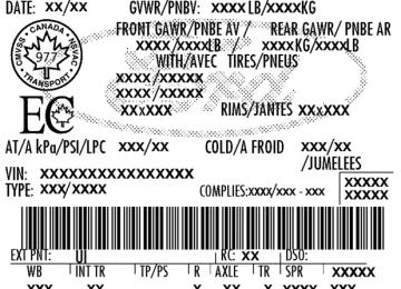
Safety Compliance Label
If you have a dissimilar spare tire/wheel, then it is intended for temporary use only. This means that if you need to use it, you should replace it as soon as possible with a road tire/wheel that is the same size and type as the road tires and wheels that were originally provided by Ford. If the dissimilar spare tire or wheel is damaged, it should be replaced rather than repaired. A dissimilar spare tire/wheel is defined as a spare tire and/or wheel that is different in brand, size or appearance from the road tires and wheels and can be one of three types: 1. T-type mini-spare: This spare tire begins with the letter “T” for tire size and may have “Temporary Use Only” molded in the sidewall 2. Full-size dissimilar spare with label on wheel: This spare tire has a label on the wheel that states: “THIS TIRE AND WHEEL FOR TEMPORARY USE ONLY” When driving with one of the dissimilar spare tires listed above, do not: • Exceed 50 mph (80 km/h) • Load the vehicle beyond maximum vehicle load rating listed on the • Tow a trailer • Use snow chains on the end of the vehicle with the dissimilar spare • Use more than one dissimilar spare tire at a time • Use commercial car washing equipment • Try to repair the dissimilar spare tire Use of one of the dissimilar spare tires listed above at any one wheel location can lead to impairment of the following: • Handling, stability and braking performance • Comfort and noise • Ground clearance and parking at curbs • Winter weather driving capability • Wet weather driving capability • All-wheel driving capability (if applicable) 3. Full-size dissimilar spare without label on wheel When driving with the full-size dissimilar spare tire/wheel, do not: • Exceed 70 mph (113 km/h)
tire
203
PAGE POSITION: 203
JOB: @zeta.tweddle.com/ford_pdm/ford/own2002/835536-en-tst/og
pubnum:
2012 Transit Connect (tst) Owners Guide, 1st Printing USA (fus)
Roadside Emergencies • Use more than one dissimilar spare tire/wheel at a time • Use commercial car washing equipment • Use snow chains on the end of the vehicle with the dissimilar spare
tire/wheel
The usage of a full-size dissimilar spare tire/wheel can lead to impairment of the following: • Handling, stability and braking performance • Comfort and noise • Ground clearance and parking at curbs • Winter weather driving capability