- 2015 Ford Escape Owners Manuals
- Ford Escape Owners Manuals
- 2009 Ford Escape Owners Manuals
- Ford Escape Owners Manuals
- 2010 Ford Escape Owners Manuals
- Ford Escape Owners Manuals
- 2004 Ford Escape Owners Manuals
- Ford Escape Owners Manuals
- 2006 Ford Escape Owners Manuals
- Ford Escape Owners Manuals
- 2011 Ford Escape Owners Manuals
- Ford Escape Owners Manuals
- 2007 Ford Escape Owners Manuals
- Ford Escape Owners Manuals
- 2003 Ford Escape Owners Manuals
- Ford Escape Owners Manuals
- 2016 Ford Escape Owners Manuals
- Ford Escape Owners Manuals
- 2001 Ford Escape Owners Manuals
- Ford Escape Owners Manuals
- 2013 Ford Escape Owners Manuals
- Ford Escape Owners Manuals
- 2014 Ford Escape Owners Manuals
- Ford Escape Owners Manuals
- 2012 Ford Escape Owners Manuals
- Ford Escape Owners Manuals
- 2002 Ford Escape Owners Manuals
- Ford Escape Owners Manuals
- Download PDF Manual
-
Always use caution while reversing. Objects in the red zone are closest to your vehicle and objects in the green zone are farther away. Objects are getting closer to your vehicle as they move from the green zone to the yellow or red zones. Use the side view mirrors and rear view mirror to get better coverage on both sides and rear of the vehicle. Selectable settings for this feature are ACTIVE + FIXED, FIXED and OFF. Visual Park Aid Alert Note: Visual park alert is only available when the transmission is in R (Reverse). Note: The reverse sensing system is not effective at speeds above 3 mph (5 km/h) and may not detect certain angular or moving objects. The system uses red, yellow and green highlights which appear on top of the video image when an object is detected by the reverse sensing system. The alert highlights the closest object detected. The reverse sensing alert can be disabled and if visual park aid alert is enabled, highlighted areas are still displayed. Selectable settings for this feature are ON and OFF. Manual Zoom
WARNING
When manual zoom is on, the full area behind the vehicle is not shown. Be aware of your surroundings when
using the manual zoom feature.
Note: Manual zoom is only available when the transmission is in R (Reverse). Note: When manual zoom is enabled, only the centerline is shown.
171
Escape (TM2)
Cruise Control
PRINCIPLE OF OPERATION Cruise control lets you maintain a set speed without keeping your foot on the accelerator pedal. USING CRUISE CONTROL
WARNINGS
Do not use cruise control in heavy traffic, on winding roads or when the road surface is slippery. When you are going downhill, your speed may increase above the set speed. The system will not apply the brakes. Change down a gear to assist the system in maintaining the set speed.
Note: Cruise control will disengage if your vehicle speed decreases more than 10 mph (16 km/h) below your set speed while driving uphill.
Setting a Speed 1. Accelerate to the desired speed. 2. Press and release SET+. 3. Take your foot off the accelerator
pedal.
Changing the Set Speed • Press and hold SET+ or SET-. Release the control when you reach the desired speed.
• Press and release SET+ or SET-. The set speed will change in approximately 1 mph (2 km/h) increments.
• Press the accelerator or brake pedal
until you reach the desired speed. Press and release SET+.
Canceling the Set Speed Pull CAN toward you and release, or tap the brake pedal. The set speed will not be erased. Resuming the Set Speed Pull RES toward you and release. Switching Cruise Control Off Note: You will erase the set speed if you switch the system off. Press and release OFF or switch the ignition off.
(cid:40)(cid:20)(cid:23)(cid:21)(cid:23)(cid:22)(cid:26) The cruise controls are located on the steering wheel. Switching Cruise Control On Press and release ON.
The indicator will display in the instrument cluster.
(cid:40)(cid:26)(cid:20)(cid:22)(cid:23)(cid:19)
172
Escape (TM2)
Driving Aids
BLIND SPOT MONITOR Blind Spot Information System (BLIS®) with Cross Traffic Alert (If Equipped)
WARNING
To help avoid injuries, NEVER use the BLIS as a replacement for using the interior and exterior mirrors and
looking over your shoulder before changing lanes. BLIS is not a replacement for careful driving and only an assist.
(cid:36)
(cid:36)
(cid:40)(cid:20)(cid:21)(cid:23)(cid:26)(cid:27)(cid:27) BLIS aids you in detecting vehicles that may have entered the blind spot zone (A). The detection area is on both sides of the vehicle, extending rearward from the exterior mirrors to approximately 10 feet (3 meters) beyond the bumper. The system is designed to alert you if certain vehicles enter the blind spot zone while driving. Cross Traffic Alert is designed to warn you of vehicles approaching from the sides when the transmission is in R (Reverse).
Note: BLIS is not designed to prevent contact with other vehicles or objects; or to detect parked vehicles, people, animals or infrastructure (fences, guardrails, trees, etc.). It is designed to alert the driver to vehicles in the blind zones. Note: When a vehicle passes quickly through the blind zone, typically fewer than two seconds, the system does not trigger. Using the Systems BLIS turns on when the engine is started and the vehicle is driven forward above 3
mph (5 km/h); it remains on while the transmission is in D (Drive) and N (Neutral). If shifted out of D (Drive) or N (Neutral), the system enters cross traffic alert mode. Once shifted back into D (Drive), BLIS turns back on when the vehicle is driven above 3 mph (5 km/h). Note: BLIS does not function in R (Reverse) or P (Park) or provide any additional warning when a turn signal is on. Cross traffic alert is designed to detect approaching vehicles from up to 45 feet (14
meters) away though coverage decreases when the sensors are blocked. Reversing slowly helps increase the coverage area and effectiveness.WARNING
To help avoid personal injury, NEVER use the cross traffic alert system as a replacement for using the interior and exterior mirrors and looking over your shoulder before backing out of a parking space. Cross traffic alert is not a replacement for careful driving and only an assist.
173
Escape (TM2)
Driving Aids
(cid:40)(cid:20)(cid:23)(cid:21)(cid:23)(cid:23)(cid:19)
In this first example, the left sensor is only partially obstructed; zone coverage is nearly maximized.
(cid:40)(cid:20)(cid:23)(cid:21)(cid:23)(cid:23)(cid:20)
Zone coverage also decreases when parking at shallow angles. Here, the left sensor is mostly obstructed; zone coverage on that side is severely limited.
174
Escape (TM2)
Driving Aids
System Lights and Messages
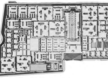
(cid:40)(cid:20)(cid:23)(cid:21)(cid:23)(cid:23)(cid:22) The system uses radar sensors which are located behind the bumper fascia on each side of your vehicle. Do not allow these areas to become obstructed by mud, snow or bumper stickers, as this can cause degraded system performance. If the system detects a degraded performance condition, a message warning of a blocked sensor or a message warning of low visibility will appear in the information display along with a warning indicator. The information display warning can be cleared but the warning indicator will remain illuminated. When the blockage is removed, the system can be reset in two ways: • when at least two objects are detected
while driving, or turn the ignition from on to off, then back on.
•
If the blockage is still present after the key cycle, the system senses again that it is blocked after driving in traffic.
(cid:40)(cid:20)(cid:23)(cid:21)(cid:23)(cid:23)(cid:21) The BLIS and Cross Traffic Alert systems illuminate a yellow alert indicator in the outside mirror on the side of the vehicle the approaching vehicle is coming from. Note: The alert indicator dims when nighttime darkness is detected. Cross Traffic Alert also sounds a series of tones and a message appears in the information display indicating a vehicle is coming from the right or left. Cross Traffic Alert works with the reverse sensing system which sounds its own series of tones. See Parking Aid (page 163). System Sensors
WARNING
Just prior to the system recognizing a blocked condition and alerting the driver, the number of missed objects will increase. To help avoid injuries, NEVER use the BLIS as a replacement for using the side and rear view mirrors and looking over your shoulder before changing lanes. BLIS is not a replacement for careful driving and only an assist.
Note: It is possible to get a blockage warning with no blockage present; this is rare and known as a false blockage warning. A false blocked condition either self-corrects or clears after a key cycle.
175
Escape (TM2)
Driving Aids
• Driving in reverse faster than 3 mph (5
km/h). Backing out of an angled parking spot.
• False Alerts Note: If the vehicle has a factory equipped tow bar, and it is towing a trailer, the sensors will detect the trailer and turn the BLIS and Cross Traffic Alert off to avoid false alerts. For non-factory equipped tow bars you may want to turn the BLIS off manually. There may be certain instances when either the BLIS or Cross Traffic Alert systems illuminate the alert indicator with no vehicle in the coverage zone; this is known as a false alert. Some amount of false alerts are normal; they are temporary and self-correct. System Errors If either system senses a problem with the left or right sensor, the BLIS telltale illuminates and remains on and the following will appear in the information display: • • Cross Traffic malfunction Service req’d Switching the Systems Off and On One or both systems can be switched off temporarily by using the information display control. See General Information (page 85). When the BLIS is switched off, you will not receive alerts and a telltale illuminates in the information display. The system switches back on whenever the ignition is switched on. One or both systems can also be switched off permanently at your authorized dealer. Once switched off, switching it back on must also be done at your authorized dealer.
BLIS: X sensor fault Service req’d or
Reasons for messages being displayed The radar Clean the fascia area in surface is dirty or
front of the radar or remove
the obstruction.
obstructed The radar surface is not dirty or obstructed
Drive normally in traffic for a few minutes to allow the
radar to detect passing
vehicles so it can clear the
blocked state.
Heavy rain- fall/snow- fall inter- feres with the radar signals
No action required. The system automatically resets to an unblocked state once the rainfall or snowfall rate decreases or stops. Do not use BLIS or Cross Traffic Alert in these
conditions.
System Limitations The BLIS and Cross Traffic Alert systems do have their limitations; situations such as severe weather conditions or debris build-up on the sensor area may limit vehicle detection. The following are other situations that may limit the BLIS: • Certain maneuvering of vehicles
entering and exiting the blind zone.
• Vehicles passing through the blind zone
at very fast rates.
• When several vehicles forming a
convoy pass through the blind zone.
The following are other situations that may limit the Cross Traffic Alert system: • Adjacently parked vehicles or objects
obstructing the sensors.
• Approaching vehicles passing at
speeds greater than 15 mph (24 km/h).
176
Escape (TM2)
Driving Aids
Anticipation Adjust your vehicle speed and the distance to other vehicles to avoid the need for heavy braking or acceleration to improve fuel economy. Efficient speed Reduce your cruising speed on open roads to improve economy. Higher speeds use more fuel. Type 2 and 3
The relevant information is shown in the display. Resetting Eco Mode Reset the average fuel consumption by using the information display control. Note: New values may take a short time to calculate STEERING Electric Power Steering WARNINGSThe electric power steering system has diagnostic checks that continuously monitor the system to ensure proper operation. When a system error is detected a steering message will appear in the information display.
The electric power steering system has diagnostic checks that continuously monitor the system to ensure proper operation of the electronic system. When an electronic error is detected, a message will be displayed in the information display. If this happens, stop the vehicle in a safe place, and turn
ECO MODE This system assists you in driving more efficiently by constantly monitoring characteristics of gear changing, anticipation of traffic conditions and speeds while driving. The value of these characteristics is represented by petals shown in the display, with five petals being the most efficient. The more efficiently you drive, the better the rating, and the better your overall fuel economy Note: These efficiency values do not result in a defined fuel consumption figure. It might vary as it is not only related to these driving habits, but also influenced by many other factors such as short trips and cold starts. Note: Frequent short trips, where the engine does not fully warm up, will also increase fuel consumption The system is accessed using the information display control. See General Information (page 85). Type 1
(cid:40)(cid:20)(cid:23)(cid:21)(cid:23)(cid:23)(cid:23)
Anticipation Efficient speed
177
Escape (TM2)
Driving Aids
WARNINGS
off the engine. After at least 10 seconds, reset the system by restarting the engine, and watch the information display for a steering message. If a steering message returns, or returns while driving, take the vehicle to your dealer to have it checked. Obtain immediate service if a system error is detected. You may not notice any difference in the feel of your
steering, but a serious condition may exist. Failure to do so may result in loss of steering control.
Your vehicle is equipped with an electric power-assisted steering system. There is no fluid reservoir to check or fill. If your vehicle loses electrical power while you are driving (or if the ignition is turned off), you can steer the vehicle manually, but it takes more effort. Extreme continuous steering may increase the effort it takes for you to steer. This occurs to prevent internal overheating and permanent damage to your steering system. If this should occur, you will neither lose the ability to steer the vehicle manually nor will it cause permanent damage. Typical steering and driving maneuvers will allow the system to cool and steering assist will return to normal. Steering Tips If the steering wanders or pulls, check for: • • • • • A high crown in the road or high crosswinds may also make the steering seem to wander or pull.
an improperly inflated tire uneven tire wear loose or worn suspension components loose or worn steering components improper vehicle alignment
178
Escape (TM2)
Load Carrying
REAR UNDER FLOOR STORAGE Passenger Compartment Floor
Adjustable Load Floor (If Equipped)
(cid:40)(cid:26)(cid:27)(cid:19)(cid:28)(cid:26) The under floor storage compartment is located behind the front passenger seat. Cargo Management System (If Equipped)
(cid:40)(cid:20)(cid:23)(cid:21)(cid:23)(cid:23)(cid:25) Vehicles with the standard size spare tire can adjust the load floor to two positions. The front of the load floor can be placed either on (for high position) or below (for low position) the ledges behind the rear seats. The rear of the load floor always sits on the two small shelves located on the liftgate trim. LUGGAGE COVERS WARNINGS
Make sure that the posts are properly latched in mounting features. The cover may cause injury in a sudden
stop or accident if it is not securely installed.
Do not place any objects on the cargo area shade. They may obstruct your vision or strike occupants of your vehicle in a sudden stop or crash.
Use the cargo shade to cover items in the cargo area of your vehicle.
(cid:40)(cid:20)(cid:23)(cid:21)(cid:23)(cid:23)(cid:24) The system is located in the floor of the cargo area. Lift the handle to open.
179
Escape (TM2)
Load Carrying
Note: Never place loads directly on the roof panel. The roof panel is not designed to directly carry a load. For correct roof rack system function, you must place loads directly on crossbars affixed to the roof rack side rails. When using the roof rack system, we recommend you use Ford Genuine Accessory crossbars designed specifically for your vehicle. Make sure that you securely fasten the load. Check the tightness of the load before driving and at each fuel stop. Adjusting the Crossbar (If Equipped) Note: For less wind noise and better aerodynamics, only install the crossbars when you need them for carrying cargo. If you prefer to keep the crossbars installed, the front crossbar has two positions. The front position is quieter for wind noise. The rear position may help to reduce wind noise from an open moonroof. Follow the steps to reposition or remove the front crossbar. You can remove the rear crossbar fasteners by unscrewing the assembly.
(cid:40)(cid:20)(cid:23)(cid:21)(cid:23)(cid:23)(cid:27) 1. Remove the crossbar thumbwheels at
both sides of the front crossbar by turning them counterclockwise.
(cid:40)(cid:20)(cid:23)(cid:21)(cid:23)(cid:23)(cid:26) Insert the ends of the cargo shade into the mounting features located behind the rear seat on the rear trim panels to install the cargo shade. To operate the cargo shade: 1. Pull the rear edge of the cargo shade
rearward.
2. Secure both ends of the support rod into the retention slots located on the rear quarter trim panels.
ROOF RACKS AND LOAD CARRIERS
WARNING
When loading the roof racks, we recommend you evenly distribute the load, as well as maintain a low
center of gravity. Loaded vehicles, with higher centers of gravity, may handle differently than unloaded vehicles. Take extra precautions, such as slower speeds and increased stopping distance, when driving a heavily loaded vehicle.
The maximum recommended load, evenly distributed on the crossbars, is: •
100 pounds (45 kilograms) for vehicles without a moonroof 45 pounds (20 kilograms) for vehicles with a moonroof.
•
180
Escape (TM2)
Load Carrying
vehicle will provide maximum return of vehicle design performance. Before loading your vehicle, familiarize yourself with the following terms for determining your vehicle’s weight ratings, with or without a trailer, from the vehicle’s Tire Label or Safety Compliance Certification Label: Base Curb Weight - is the weight of the vehicle including a full tank of fuel and all standard equipment. It does not include passengers, cargo, or optional equipment. Vehicle Curb Weight - is the weight of your new vehicle when you picked it up from your authorized dealer plus any aftermarket equipment.
Note: If you cannot loosen the thumbwheel with your hand, loosen the fastener head. You can also use a small screwdriver or similar tool to loosen the thumbwheel by inserting the shaft between the two paddles of the thumbwheel and rotating it loose. 2. Remove the crossbar by sliding the ends off of the shoulder bolts in the side rails.
3. Move the crossbar to the new side rail
position and slide the crossbar onto the shoulder bolt at that position.
4. Replace and tighten the thumbwheels at both sides of the crossbar by turning them clockwise until tight. You can use a small screwdriver or similar tool to tighten if necessary.
Make sure to check that the thumbwheels are tight each time you add or remove load from the roof rack, and periodically while traveling. Make sure that the load is secure before traveling. LOAD LIMIT Vehicle Loading - with and without a Trailer This section will guide you in the proper loading of your vehicle, trailer or both, to keep your loaded vehicle weight within its design rating capability, with or without a trailer. Properly loading your
181
Escape (TM2)
Load Carrying
(cid:51)(cid:36)(cid:60)(cid:47)(cid:50)(cid:36)(cid:39)
(cid:40)(cid:20)(cid:23)(cid:22)(cid:27)(cid:20)(cid:25)
Payload - is the combined weight of cargo and passengers that the vehicle is carrying. The maximum payload for your vehicle can be found on the Tire Label on the B-Pillar or the edge of the driver door (vehicles exported outside the US and Canada may not have a Tire Label). Look for “THE COMBINED WEIGHT OF OCCUPANTS AND CARGO SHOULD NEVER EXCEED XXX kg OR XXX lb.” for maximum payload. The payload listed on the Tire Label is the maximum payload for the vehicle as built by the assembly plant. If you install
any aftermarket or authorized-dealer installed equipment on the vehicle, you must subtract the weight of the equipment from the payload listed on the Tire Label in order to determine the new payload.
WARNING
The appropriate loading capacity of your vehicle can be limited either by volume capacity (how much space is available) or by payload capacity (how much weight the vehicle should carry). Once you have reached the maximum payload of your vehicle, do not add more cargo, even if there is space available. Overloading or improperly loading your vehicle can contribute to loss of vehicle control and vehicle rollover.
182
Escape (TM2)
Load Carrying
183
Example only:
(cid:40)(cid:20)(cid:23)(cid:21)(cid:24)(cid:20)(cid:25)
(cid:40)(cid:20)(cid:23)(cid:21)(cid:24)(cid:20)(cid:26)
(cid:38)(cid:36)(cid:53)(cid:42)(cid:50)
(cid:40)(cid:20)(cid:23)(cid:22)(cid:27)(cid:20)(cid:26)
Escape (TM2)
Load Carrying
Cargo Weight - includes all weight added to the Base Curb Weight, including cargo and optional equipment. When towing, trailer tongue load or king pin weight is also part of cargo weight. GAW (Gross Axle Weight) - is the total weight placed on each axle (front and rear) including vehicle curb weight and all payload.
GAWR (Gross Axle Weight Rating) - is the maximum allowable weight that can be carried by a single axle (front or rear). These numbers are shown on the Safety Compliance Certification Label. The label shall be affixed to either the door hinge pillar, door-latch post, or the door edge that meets the door-latch post, next to the driver's seating position. The total load on each axle must never exceed its Gross Axle Weight Rating. Note: For trailer towing information refer to the RV and Trailer Towing Guide available at an authorized dealer.
(cid:42)(cid:57)(cid:58)
(cid:40)(cid:20)(cid:23)(cid:22)(cid:27)(cid:20)(cid:27)
GVW (Gross Vehicle Weight) - is the Vehicle Curb Weight, plus cargo, plus passengers. GVWR (Gross Vehicle Weight Rating) - is the maximum allowable weight of the fully loaded vehicle (including all options, equipment, passengers and cargo). It is shown on the
Safety Compliance Certification Label. The label shall be affixed to either the door hinge pillar, door-latch post, or the door edge that meets the door-latch post, next to the driver's seating position. The Gross Vehicle Weight must never exceed the Gross Vehicle Weight Rating.
184
Escape (TM2)
Load Carrying
Example only:
(cid:40)(cid:20)(cid:23)(cid:21)(cid:24)(cid:21)(cid:22)
(cid:40)(cid:20)(cid:23)(cid:21)(cid:24)(cid:21)(cid:23)
WARNING
Exceeding the Safety Compliance Certification Label vehicle weight rating limits could result in substandard vehicle handling or performance, engine, transmission and/or structural damage, serious damage to the vehicle, loss of control and personal injury.
185
Escape (TM2)
Load Carrying
Maximum Loaded Trailer Weight - is the highest possible weight of a fully loaded trailer the vehicle can tow. It assumes a vehicle with mandatory options, driver and front passenger weight (150 pounds [68 kilograms] each), no cargo weight (internal or external) and a tongue load of 10–15% (conventional trailer) or king pin weight of 15–25% (fifth wheel trailer). Consult an authorized dealer (or the RV and Trailer Towing Guide available at an authorized dealer) for more detailed information. Tongue Load or Fifth Wheel King Pin Weight - refers to the amount of the weight that a trailer pushes down on a trailer hitch.
(cid:42)(cid:38)(cid:58)
(cid:42)(cid:57)(cid:58)
(cid:40)(cid:20)(cid:23)(cid:22)(cid:27)(cid:20)(cid:28)
GCW (Gross Combined Weight) - is the Gross Vehicle Weight plus the weight of the fully loaded trailer. GCWR (Gross Combined Weight Rating) - is the maximum allowable weight of the vehicle and the loaded trailer, including all cargo and passengers, that the vehicle can handle without risking damage. (Important: The towing vehicle’s braking system is rated for operation at Gross Vehicle Weight Rating, not at Gross Combined Weight Rating.) Separate functional brakes should be used for safe control of towed vehicles and for trailers where the Gross Combined Weight of the towing vehicle plus the trailer exceed the Gross Vehicle Weight Rating of the towing vehicle. The Gross Combined Weight must never exceed the Gross Combined Weight Rating.
186
Escape (TM2)
Load Carrying
3. Subtract the combined weight of the driver and passengers from XXX kg or XXX lb. 4. The resulting figure equals the available amount of cargo and luggage load capacity. For example, if the “XXX” amount equals 1,400 lb. and there will be five 150 lb. passengers in your vehicle, the amount of available cargo and luggage load capacity is 650 lb. (1400-750 (5 x 150) = 650 lb.) 5. Determine the combined weight of luggage and cargo being loaded on the vehicle. That weight may not safely exceed the available cargo and luggage load capacity calculated in Step 4. 6. If your vehicle will be towing a trailer, load from your trailer will be transferred to your vehicle. Consult this manual to determine how this reduces the available cargo and luggage load capacity of your vehicle. The following gives you a few examples on how to calculate the available amount of cargo and luggage load capacity: *Suppose your vehicle has a 1400-pound (635-kilogram) cargo and luggage capacity. You decide to go golfing. Is there enough load capacity to carry you, four of your friends and all the golf bags? You
Examples: For a 5000 pound (2268 kilogram) conventional trailer, multiply 5000 by 0.10 and 0.15 to obtain a proper tongue load range of 500 to 750 pounds (227 to 340 kilograms). For an 11500 pound (5216 kilogram) fifth wheel trailer, multiply by 0.15 and 0.25 to obtain a proper king pin load range of 1725 to 2875 pounds (782 to 1304 kilograms).
WARNINGS
Do not exceed the GVWR or the GAWR specified on the Safety Compliance Certification Label. Do not use replacement tires with lower load carrying capacities than the original tires because they may
lower the vehicle’s GVWR and GAWR limitations. Replacement tires with a higher limit than the original tires do not increase the GVWR and GAWR limitations.
Exceeding any vehicle weight rating limitation could result in serious damage to the vehicle and/or
personal injury. Steps for determining the correct load limit: 1. Locate the statement "The combined weight of occupants and cargo should never exceed XXX kg or XXX lb." on your vehicle’s placard. 2. Determine the combined weight of the driver and passengers that will be riding in your vehicle.
187
Escape (TM2)
Load Carrying
and four friends average 220
pounds (99 kilograms) each and the golf bags weigh approximately 30 pounds (13.5 kilograms) each. The calculation would be: 1400 - (5 x 220) - (5 x 30) = 1400 - 1100
- 150 = 150 pounds. Yes, you have enough load capacity in your vehicle to transport four friends and your golf bags. In metric units, the calculation would be: 635
kilograms - (5 x 99 kilograms) - (5 x 13.5 kilograms) = 635 - 495 - 67.5 = 72.5 kilograms. *Suppose your vehicle has a 1400-pound (635-kilogram) cargo and luggage capacity. You and one of your friends decide to pick up cement from the local home improvement store to finish that patio you have been planning for the past two years. Measuring the inside of the vehicle with the rear seat folded down, you have room for twelve 100-pound (45-kilogram) bags of cement. Do you have enough load capacity to transport the cement to your home? If you and your friend each weigh 220 pounds (99 kilograms), the calculation would be: 1400 - (2 x 220) - (12 x 100) = 1400 - 440
- 1200 = - 240 pounds. No, you do not have enough cargo capacity to carry that much weight. In metric units, the calculation would be: 635 kilograms - (2 x 99
kilograms) - (12 x 45 kilograms) =635 - 198 - 540 = -103 kilograms. You will need to reduce the load weight by at least 240 pounds (104 kilograms). If you remove three 100-pound (45-kilogram) cement bags, then the load calculation would be:1400 - (2 x 220) - (9 x 100) = 1400 - 440 - 900 = 60 pounds. Now you have the load capacity to transport the cement and your friend home. In metric units, the calculation would be: 635 kilograms - (2 x 99
kilograms) - (9 x 45 kilograms) = 635 - 198 - 405 = 32 kilograms. The above calculations also assume that the loads are positioned in your vehicle in a manner that does not overload the Front or the Rear Gross Axle Weight Rating specified for your vehicle on the Safety Compliance Certification Label. The label shall be affixed to either the door hinge pillar, door-latch post, or the door edge that meets the door-latch post, next to the driver's seating position. Special Loading Instructions for Owners of Pick-up Trucks and Utility-type VehiclesWARNING
Loaded vehicles may handle differently than unloaded vehicles. Extra precautions, such as slower
speeds and increased stopping distance, should be taken when driving a heavily loaded vehicle.
188
Escape (TM2)
Load Carrying
Your vehicle can haul more cargo and people than most passenger cars. Depending upon the type and placement of the load, hauling cargo and people may raise the center of gravity of the vehicle.
189
Escape (TM2)
Towing
•
•
Load the heaviest items above the trailer axles or just slightly forward toward the trailer tongue. Do not allow the final trailer tongue weight to go above or below 10-15% of the loaded trailer weight. Select a tow bar with the correct rise or drop. When both the loaded vehicle and trailer are connected, the trailer frame should be level, or slightly angled down toward your vehicle, when viewed from the side.
When driving with a trailer or payload, a slight takeoff vibration or shudder may be present due to the increased payload weight. Additional information regarding proper trailer loading and setting your vehicle up for towing is located in another chapter of this manual. See Load Limit (page 181). You can also find the information in the RV & Trailer Towing Guide, available at an authorized dealer. TRAILER SWAY CONTROL (IF EQUIPPED) Note: This feature does not prevent trailer sway, but reduces it once it begins. Note: This feature cannot stop all trailers from swaying. Note: In some cases, if vehicle speed is too high, the system may activate multiple times, gradually reducing vehicle speed. This feature applies the vehicle brakes at individual wheels and, if necessary, reduces engine power. If the trailer begins to sway, the stability control light flashes. The first thing to do is slow the vehicle down, then pull safely to the side of the road and check for proper tongue load and trailer load distribution. See Load Carrying (page 179).
TOWING A TRAILER WARNINGS
Do not exceed the GVWR or the GAWR specified on the certification label. Towing trailers beyond the maximum recommended gross trailer weight exceeds the limit of the vehicle and
could result in engine damage, transmission damage, structural damage, loss of vehicle control, vehicle rollover and personal injury.
Your vehicle may have electrical items, such as fuses or relays, related to towing. See the Fuses chapter. Your vehicle's load capacity designation is by weight, not by volume, so you cannot necessarily use all available space when loading a vehicle. Towing a trailer places an extra load on your vehicle's engine, transmission, axle, brakes, tires and suspension. Inspect these components periodically during, and after, any towing operation. Load Placement To help minimize how trailer movement affects your vehicle when driving: •
Load the heaviest items closest to the trailer floor. Load the heaviest items centered between the left and right side trailer tires.
•
190
Escape (TM2)
Towing
RECOMMENDED TOWING WEIGHTS Note: Do not exceed the trailer weight for your vehicle configuration listed in the chart below. Note: Be sure to take into consideration trailer frontal area. Do not exceed 20 feet2
(1.86 meters2) if your vehicle is not equipped with a towing package or 30 feet2 (2.79
meters2) if your vehicle is equipped with a towing package. Note: For high altitude operation, reduce the gross combined weight by 2% per 1000
feet (300 meters) starting at the 1000 foot (300 meter) elevation point.Note: Certain states require electric trailer brakes for trailers over a specified weight. Be sure to check state regulations for this specified weight. The maximum trailer weights listed may be limited to this specified weight, as the vehicle’s electrical system may not include the wiring connector needed to activate electric trailer brakes. Your vehicle may tow a Class I or II trailer provided the maximum trailer weight is less than or equal to the maximum trailer weight listed for your vehicle configuration on the following chart.
Powertrain
Maximum GCWR - lb (kg)
Maximum Trailer Weight - lb
(kg)1
2.5L 2WD 1.6L GTDI 2WD
2.0L GTDI 2WD2
1.6L GTDI 4WD2.0L GTDI 4WD2
2.0L GTDI 2WD3
2.0L GTDI 4WD3
1Calculated with SAE J2807 method. 2Without trailer towing package. 3 With trailer towing package.5351 (2427) 5862 (2659) 5957 (2702)
6005 (2724) 6091 (2763)
7457 (3382)
7591 (3443)
1500 (681) 2000 (907) 2000 (907)
2000 (907) 2000 (907)
3500 (1588)
3500 (1588)
191
Escape (TM2)
Towing
Trailer Brakes
WARNING
Do not connect a trailer's hydraulic brake system directly to your vehicle's brake system. Your vehicle may not have enough braking power and your chances of having a collision greatly increase.
Electric brakes and manual, automatic or surge-type trailer brakes are safe if you install them properly and adjust them to the manufacturer's specifications. The trailer brakes must meet local and federal regulations. The rating for the tow vehicle's braking system operation is at the gross vehicle weight rating, not the gross combined weight rating. Separate functioning brake systems are required for safe control of towed vehicles and trailers weighing more than 1500 pounds (680 kilograms) when loaded. Trailer Lamps
WARNING
Never connect any trailer lamp wiring to the vehicle's tail lamp wiring; this may damage the electrical system resulting in fire. Contact your authorized dealer as soon as possible for assistance in proper trailer tow wiring installation. Additional electrical equipment may be required.
Trailer lamps are required on most towed vehicles. Make sure all running lights, brake lights, turn signals and hazard lights are working.
ESSENTIAL TOWING CHECKS Follow these guidelines for safe towing: • Do not tow a trailer until you drive your
vehicle at least 1000 miles (1600
kilometers).• Consult your local motor vehicle laws
for towing a trailer. See the instructions included with towing accessories for the proper installation and adjustment specifications. Service your vehicle more frequently if you tow a trailer. See your scheduled maintenance information. If you use a rental trailer, follow the instructions the rental agency gives you.
•
•
•
Another chapter of this manual contains load specification terms found on the tire label and Safety Compliance label and instructions on calculating your vehicle's load. See Load Limit (page 181). Remember to account for the trailer tongue weight as part of your vehicle load when calculating the total vehicle weight. Hitches Do not use a hitch that either clamps onto the bumper or attaches to the axle. Distribute the trailer load so 10-15% of the total trailer weight is on the tongue. Safety Chains Note: Never attach safety chains to the bumper. Always connect the safety chains to the hook retainers of your vehicle hitch. To connect the safety chains, cross them under the trailer tongue and allow enough slack for turning tight corners. Do not allow the chains to drag on the ground.
192
Escape (TM2)
Towing
• Allow more distance for stopping with a trailer attached. Anticipate stops and brake gradually.
• Avoid parking on a grade. However, if
you must park on a grade: •
Turn the steering wheel to point your vehicle tires away from traffic flow. Set your vehicle parking brake.
• • Place the automatic transmission
in position P.
• Place wheel chocks in front and
back of the trailer wheels. (Chocks not included with vehicle.)
Launching or Retrieving a Boat or Personal Watercraft (PWC) Note: Disconnect the wiring to the trailer before backing the trailer into the water. Note: Reconnect the wiring to the trailer after the trailer is removed from the water. When backing down a ramp during boat launching or retrieval: • Do not allow the static water level to rise above the bottom edge of the rear bumper.
• Do not allow waves to break higher
than 6 inches (15 centimeters) above the bottom edge of the rear bumper.
Exceeding these limits may allow water to enter vehicle components: • Causing internal damage to the
components.
• Affecting driveability, emissions, and
reliability.
Replace the rear axle lubricant anytime the rear axle has been submerged in water. Water may have contaminated the rear axle lubricant, which is not normally checked or changed unless a leak is suspected or other axle repair is required.
Before Towing a Trailer Practice turning, stopping and backing up to get the feel of your vehicle-trailer combination before starting on a trip. When turning, make wider turns so the trailer wheels clear curbs and other obstacles. When Towing a Trailer • Do not drive faster than 70 mph (113
km/h) during the first 500 miles (800
kilometers).• Do not make full-throttle starts. • Check your hitch, electrical connections
and trailer wheel lug nuts thoroughly after you have traveled 50 miles (80
kilometers).•
• When stopped in congested or heavy traffic during hot weather, place the gearshift in position P to aid engine and transmission cooling and to help A/C performance. Turn off the speed control with heavy loads or in hilly terrain. The speed control may turn off automatically when you are towing on long, steep grades. Shift to a lower gear when driving down a long or steep hill. Do not apply the brakes continuously, as they may overheat and become less effective. If your transmission is equipped with a Grade Assist or Tow/Haul feature, use this feature when towing. This provides engine braking and helps eliminate excessive transmission shifting for optimum fuel economy and transmission cooling.
•
•
193
Escape (TM2)
Towing
TRANSPORTING THE VEHICLE
TOWING POINTS Recovery Hook Location If your vehicle is equipped with a screw-in recovery hook, it is located in the spare wheel well. If your vehicle is not equipped with a recovery hook, you can purchase one from your dealer. Installing the Recovery Hook The screw-in recovery hook has a left-hand thread. Turn it counterclockwise to install it. Make sure that the recovery hook is fully tightened.
(cid:40)(cid:20)(cid:23)(cid:25)(cid:21)(cid:27)(cid:23) Insert a suitable object to pry open the cover (1). Use recessed/notched portion of the cover. Screw in the recovery hook (2). Towing the Vehicle on Four Wheels Switch the ignition to the on position. Failure to do so results in steering lock and non-function of indicator and brake lamps. Braking and steering efforts are high if the engine is not running. Maintain increased stopping distances.
(cid:40)(cid:20)(cid:23)(cid:22)(cid:27)(cid:27)(cid:25) If you need to have your vehicle towed, contact a professional towing service or, if you are a member of a roadside assistance program, your roadside assistance service provider. We recommend the use of a wheel lift and dollies or flatbed equipment to tow your vehicle. Do not tow with a slingbelt. Ford Motor Company has not approved a slingbelt towing procedure. Vehicle damage may occur if towed incorrectly, or by any other means. Ford Motor Company produces a towing manual for all authorized tow truck operators. Have your tow truck operator refer to this manual for proper hook-up and towing procedures for your vehicle.
194
Escape (TM2)
Towing
Recreational Towing Note: Put your climate control system in recirculated air mode to prevent exhaust fumes from entering the vehicle. See Climate Control (page 115). Follow these guidelines if you have a need for recreational (RV) towing. An example of recreational towing would be towing your vehicle behind a motorhome. We designed these guidelines to prevent damage to your transmission. Front-wheel drive vehicles CANNOT be flat-towed (all wheels on the ground) as vehicle or transmission damage may occur. You must place the front wheels on a two-wheel tow dolly. If you are using a tow dolly, follow the instructions specified by the equipment provider. Four-wheel drive vehicles CANNOT be flat-towed (all wheels on the ground), as vehicle or transmission damage may occur. It is recommended to tow your vehicle with all four (4) wheels off the ground such as when using a car-hauling trailer. Otherwise, you cannot recreational tow your vehicle.
It is acceptable to have your front-wheel drive vehicle towed from the front if using proper wheel lift equipment to raise the front wheels off the ground. When towing in this manner, the rear wheels can remain on the ground. Front-wheel drive vehicles must have the front wheels placed on a tow dolly when towing your vehicle from the rear using wheel lift equipment. This prevents damage to the transmission. Towing a four-wheel drive vehicle requires that all wheels be off the ground, such as using a wheel lift and dollies or flatbed equipment. This prevents damage to the transmission, four-wheel drive system and vehicle. TOWING THE VEHICLE ON FOUR WHEELS Emergency Towing If your vehicle becomes inoperable (without access to wheel dollies, car-hauling trailer, or flatbed transport vehicle), it can be flat-towed (all wheels on the ground, regardless of the powertrain and transmission configuration) under the following conditions: •
Your vehicle is facing forward for towing in a forward direction.
• Place the transmission in position N. If you cannot move the transmission into N, you may need to override it. See Transmission (page 150).
• Maximum speed is 35 mph (56 km/h). • Maximum distance is 50 miles (80
kilometers).
195
Escape (TM2)
Driving Hints
There are also some things you may not want to do because they may reduce your fuel economy: •
Sudden accelerations or hard accelerations.
• Rev the engine before turning it off. • • Warm up your vehicle on cold
Idle for periods longer than one minute.
mornings.
• Use the air conditioner or front
defroster.
• Use the speed control in hilly terrain. • Rest your foot on the brake pedal while
driving.
• Drive a heavily loaded vehicle or tow a
trailer.
• Carry unnecessary weight
(approximately 1 mpg [0.4 km/L] is lost for every 400 lb [180 kg] of weight carried).
• Add particular accessories to your
vehicle (e.g. bug deflectors, rollbars/light bars, running boards, ski racks).
• Drive with the wheels out of alignment. DRIVING THROUGH WATER Note: Driving through deep water above the recommended levels can cause vehicle damage. If driving through deep or standing water is unavoidable, proceed very slowly. Never drive through water that is higher than the bottom of the wheel rims (for cars) or the bottom of the hubs (for trucks).
BREAKING-IN You need to break in new tires for approximately 300 miles (480
kilometers). During this time, your vehicle may exhibit some unusual driving characteristics. Avoid driving too fast during the first 1000
miles (1600 kilometers). Vary your speed frequently and change up through the gears early. Do not labor the engine. Do not tow during the first 1000 miles (1600 kilometers). ECONOMICAL DRIVING Fuel economy is affected by several things such as how you drive, the conditions you drive under and how you maintain your vehicle. There are some things to keep in mind that may improve your fuel economy: • Accelerate and slow down in a smooth,moderate fashion.
• Drive at steady speeds without
stopping.
• Anticipate stops; slowing down may
eliminate the need to stop.
• Combine errands and minimize
stop-and-go driving.
• Close the windows for high-speed
driving.
• Drive at reasonable speeds (traveling at 55 mph [88 km/h] uses 15% less fuel than traveling at 65 mph [105
km/h]). Keep the tires properly inflated and use only the recommended size.•
• Use the recommended engine oil. • Perform all regularly scheduled
maintenance.
196
Escape (TM2)
Driving Hints
WARNINGS
Always use floor mats that are designed to fit the foot well of your vehicle. Only use floor mats that
leave the pedal area unobstructed. Only use floor mats that are firmly secured to retention posts so that they cannot slip out of position and interfere with the pedals or impair safe operation of your vehicle in other ways.
(cid:40)(cid:20)(cid:23)(cid:21)(cid:25)(cid:25)(cid:26) When driving through water, traction or brake capability may be limited. Also, water may enter your engine’s air intake and severely damage your engine or your vehicle may stall. Once through the water, always dry the brakes by moving your vehicle slowly while applying light pressure on the brake pedal. Wet brakes do not stop the vehicle as quickly as dry brakes. FLOOR MATS
(cid:40)(cid:20)(cid:23)(cid:21)(cid:25)(cid:25)(cid:25)
Escape (TM2)
Pedals that cannot move freely can cause loss of vehicle control and increase the risk of serious personal
injury.
Always make sure that the floor mats are properly attached to the retention posts in the carpet that are supplied with your vehicle. Floor mats must be properly secured to both retention posts to ensure mats do not shift out of position. Never place floor mats or any other covering in the vehicle foot well that cannot be properly secured to
prevent them from moving and interfering with the pedals or the ability to control the vehicle.
Never place floor mats or any other covering on top of already installed floor mats. Floor mats should always rest on top of vehicle carpeting surface and not another floor mat or other covering. Additional floor mats or any other covering will reduce the pedal clearance and potentially interfere with pedal operation. Check attachment of floor mats on a regular basis. Always properly reinstall and secure floor mats that
have been removed for cleaning or replacement.
Always make sure that objects cannot fall into the driver foot well while the vehicle is moving. Objects that are loose can become trapped under the pedals causing a loss of vehicle control.
197
Driving Hints
WARNINGS
Failure to properly follow floor mat installation or attachment instructions can potentially cause
interference with pedal operation causing loss of control of vehicle.
To install floor mats, position the floor mat so that the eyelet is over the retention post and press down
to lock in.
To remove the floor mat, reverse the installation procedure.
198
Escape (TM2)
Roadside Emergencies
ROADSIDE ASSISTANCE Vehicles Sold In The U.S.: Getting Roadside Assistance To fully assist you should you have a vehicle concern, Ford Motor Company offers a complimentary roadside assistance program. This program is separate from the New Vehicle Limited Warranty. The service is available: 24 hours, seven days a week. • for the coverage period listed on the • Roadside Assistance Card included in your Owner's Manual portfolio.
• •
Roadside assistance will cover: •
a flat tire change with a good spare, if provided with the vehicle (except vehicles that have been supplied with a tire inflation kit). battery jump start. lock-out assistance (key replacement cost is the customer's responsibility). fuel delivery — Independent Service Contractors, if not prohibited by state, local or municipal law, shall deliver up to 2.0 gallons (7.5 liters) of gasoline or 5.0 gallons (18.9 liters) of diesel fuel to a disabled vehicle. Fuel delivery service is limited to two no-charge occurrences within a 12-month period. • winch out — available within 100 feet
•
(30.5 meters) of a paved or county maintained road, no recoveries. towing — Ford and Lincoln eligible vehicles towed to an authorized dealer within 35 miles (56.3 kilometers) of the disablement location or to the nearest authorized dealer. If a member requests to be towed to an authorized dealer more than 35 miles (56.3
kilometers) from the disablement location, the member shall be responsible for any mileage costs in excess of 35 miles (56.3 kilometers).•
Trailers shall be covered up to $200 if the disabled eligible vehicle requires service at the nearest authorized dealer. If the trailer is disabled, but the towing vehicle is operational, the trailer does not qualify for any roadside services. Vehicles Sold In The U.S. : Using Roadside Assistance Complete the roadside assistance identification card and place it in your wallet for quick reference. This card is found in the owner's information portfolio in the glove compartment. U.S. Ford vehicle customers who require Roadside Assistance, call 1-800-241-3673. If you need to arrange roadside assistance for yourself, Ford Motor Company will reimburse a reasonable amount for towing to the nearest dealership within 35 miles (56.3 kilometers). To obtain reimbursement information, U.S. Ford vehicle customers call 1-800-241-3673. Customers will be asked to submit their original receipts. Vehicles Sold In Canada : Getting Roadside Assistance Canadian customers who require roadside assistance, call 1-800-665-2006. Vehicles Sold In Canada : Using Roadside Assistance Complete the roadside assistance identification card and place it in your wallet for quick reference. In Canada, the card is found in the warranty information in the glove box. Canadian roadside coverage and benefits may differ from the U.S. coverage. Please refer to your warranty information or visit our website at www.ford.ca for information on Canadian services and benefits.
199
Escape (TM2)
Roadside Emergencies
Canadian customers who need to obtain roadside information, call 1-800-665-2006 or visit our website at www.ford.ca. HAZARD WARNING FLASHERS Note: If used when the engine is not running, the battery will lose charge. There may be insufficient power to restart your engine.
3. Turn the ignition off. 4. Turn the ignition on again to re-enable
the fuel pump.
For vehicles equipped with a push button start system: 1. Press the START/STOP button to
turn the ignition off.
2. Press the brake pedal and press the
START/STOP button (crank attempt).
3. Remove your foot from the brake pedal and press the START/STOP button (ignition off).
4. Press the START/STOP button again
to re-enable the fuel system.
JUMP-STARTING THE VEHICLE
WARNINGS
The gases around the battery can explode if exposed to flames, sparks, or lit cigarettes. An explosion could
result in injury or vehicle damage.
Batteries contain sulfuric acid which can burn skin, eyes and clothing, if contacted. Use only an adequate-sized cable with insulated clamps.
Preparing Your Vehicle Note: Do not attempt to push-start your automatic transmission vehicle. Automatic transmissions do not have push-start capability. Attempting to push-start a vehicle with an automatic transmission may cause transmission damage. Note: Use only a 12-volt supply to start your vehicle. Note: Do not disconnect the battery of the disabled vehicle as this could damage the vehicle's electrical system.
The hazard warning button is located on the instrument panel. Use it when your vehicle is
creating a safety hazard for other motorists. • Press the button to turn on the hazard
warning function, and the front and rear direction indicators will flash.
• Press the button again to turn them
off.
FUEL SHUTOFF
WARNING
Failure to inspect and, if necessary, repair fuel leaks after a collision may increase the risk of fire and serious injury. Ford Motor Company recommends that the fuel system be inspected by an authorized dealer after any collision.
In the event of a moderate to severe collision, this vehicle is equipped with a fuel pump shut-off feature that stops the flow of fuel to the engine. Not every impact will cause a shut-off. Should your vehicle shut off after a collision, you may restart your vehicle by doing the following: 1. Turn the ignition off. 2. Turn the ignition to crank.
200
Escape (TM2)
Roadside Emergencies
1. Connect the positive (+) jumper cable
to the positive (+) terminal of the discharged battery.
2. Connect the other end of the positive (+) cable to the positive (+) terminal of the assisting battery.
3. Connect the negative (-) cable to the negative (-) terminal of the assisting battery.
4. Make the final connection of the
negative (-) cable to an exposed metal part of the stalled vehicle's engine, or connect the negative (-) cable to a ground connection point if available.
WARNING
Do not connect the end of the second cable to the negative (-) terminal of the battery to be jumped.
A spark may cause an explosion of the gases that surround the battery. Jump Starting 1. Start the engine of the booster vehicle and rev the engine moderately, or press the accelerator gently to keep your engine speed between 2000 and 3000
rpms, as shown in your tachometer.2. Start the engine of the disabled vehicle. 3. Once the disabled vehicle has been
started, run both vehicle engines for an additional three minutes before disconnecting the jumper cables. Removing the Jumper Cables Remove the jumper cables in the reverse order that they were connected.
Park the booster vehicle close to the hood of the disabled vehicle, making sure the two vehicles do not touch. Turn all accessories off. Connecting the Jumper Cables
WARNING
Do not attach the cables to fuel lines, engine rocker covers, the intake manifold or electrical components as grounding points. Stay clear of moving parts. To avoid reverse polarity connections, make sure that you correctly identify the positive (+) and negative (-) terminals on both the disabled and booster vehicles before connecting the cables.
Note: In the illustration, the bottom vehicle represents the booster vehicle.
(cid:40)(cid:20)(cid:23)(cid:21)(cid:25)(cid:25)(cid:23)
Escape (TM2)
201
Roadside Emergencies
(cid:40)(cid:20)(cid:23)(cid:21)(cid:25)(cid:25)(cid:24) 1. Remove the jumper cable from the ground metal surface or connecting point, if available.
2. Remove the jumper cable on the
negative (-) terminal of the booster vehicle's battery.
3. Remove the jumper cable from the positive (+) terminal of the booster vehicle's battery.
4. Remove the jumper cable from the positive (+) terminal of the disabled vehicle's battery.
After the disabled vehicle has been started and the jumper cables removed, allow it to idle for several minutes so the battery can recharge.
202
Escape (TM2)
Customer Assistance
These are some of the items that can be found online: • U.S. dealer locator by Dealer Name,
City/State, or Zip Code
Ford Extended Service Plans Ford Genuine Accessories Service specials and promotions.
• Owner Manuals • Maintenance Schedules • Recalls • • • In Canada: Mailing address Customer Relationship Centre Ford Motor Company of Canada, Limited P.O. Box 2000
Oakville, Ontario L6J 5E4
Telephone 1-800-565-3673 (FORD) Online www.ford.ca Additional Assistance If you have questions or concerns, or are unsatisfied with the service you are receiving, follow these steps: 1. Contact your Sales Representative or Service Advisor at your selling/servicing authorized dealer. If your inquiry or concern remains unresolved, contact the Sales Manager, Service Manager or Customer Relations Manager. If you require assistance or clarification on Ford Motor Company policies, please contact the Ford Customer Relationship Center.3.
2.
GETTING THE SERVICES YOU NEED Warranty repairs to your vehicle must be performed by an authorized dealer. While any authorized dealer handling your vehicle line will provide warranty service, we recommend you return to your selling authorized dealer who wants to ensure your continued satisfaction. Please note that certain warranty repairs require special training and equipment, so not all authorized dealers are authorized to perform all warranty repairs. This means that, depending on the warranty repair needed, you may have to take your vehicle to another authorized dealer. A reasonable time must be allowed to perform a repair after taking your vehicle to the authorized dealer. Repairs will be made using Ford or Motorcraft® parts, or remanufactured or other parts that are authorized by Ford. Away From Home If you are away from home when your vehicle needs service, contact the Ford Customer Relationship Center or use the online resources listed below to find the nearest authorized dealer. In the United States: Mailing address Ford Motor Company Customer Relationship Center P.O. Box 6248
Dearborn, MI 48121
Telephone 1-800-392-3673 (FORD) (TDD for the hearing impaired: 1-800-232-5952) Online Additional information and resources are available online at www.fordowner.com203
Escape (TM2)
Customer Assistance
California Civil Code Section 1793.22(b) presumes that the manufacturer has had a reasonable number of attempts to conform the vehicle to its applicable express warranties if, within the first 18
months of ownership of a new vehicle or the first 18000 miles (29 000 km), whichever occurs first: 1. Two or more repair attempts are made on the same non-conformity likely to cause death or serious bodily injury OR 2. Four or more repair attempts are made on the same nonconformity (a defect or condition that substantially impairs the use, value or safety of the vehicle) OR3. The vehicle is out of service for repair of nonconformities for a total of more than 30 calendar days (not necessarily all at one time).
In the case of 1 or 2 above, the consumer must also notify the manufacturer of the need for the repair of the nonconformity at the following address: Ford Motor Company 16800 Executive Plaza Drive Mail Drop 3NE-B Dearborn, MI 48126
You are required to submit your warranty dispute to BBB AUTO LINE before asserting in court any rights or remedies conferred by California Civil Code Section 1793.22(b). You are also required to use BBB AUTO LINE before exercising rights or seeking remedies created by the Federal Magnuson-Moss Warranty Act, 15 U.S.C. sec. 2301 et seq. If you choose to seek redress by pursuing rights and remedies not created by California Civil Code Section 1793.22(b) or the Magnuson-Moss Warranty Act, resort to BBB AUTO LINE is not required by those statutes.•
In order to help you serve you better, please have the following information available when contacting a Customer Relationship Center: • Vehicle Identification Number. •
Your telephone number (home and business). The name of the authorized dealer and city where located. The vehicle’s current odometer reading.
• In some states, you must directly notify Ford in writing before pursuing remedies under your state’s warranty laws. Ford is also allowed a final repair attempt in some states. In the United States, a warranty dispute must be submitted to the BBB AUTO LINE before taking action under the Magnuson-Moss Warranty Act, or to the extent allowed by state law, before pursuing replacement or repurchase remedies provided by certain state laws. This dispute handling procedure is not required prior to enforcing state created rights or other rights which are independent of the Magnuson-Moss Warranty Act or state replacement or repurchase laws. IN CALIFORNIA (U.S. ONLY) California Civil Code Section 1793.2(d) requires that, if a manufacturer or its representative is unable to repair a motor vehicle to conform to the vehicle’s applicable express warranty after a reasonable number of attempts, the manufacturer shall be required to either replace the vehicle with one substantially identical or repurchase the vehicle and reimburse the buyer in an amount equal to the actual price paid or payable by the consumer (less a reasonable allowance for consumer use). The consumer has the right to choose whether to receive a refund or replacement vehicle.
204
Escape (TM2)
Customer Assistance
THE BETTER BUSINESS BUREAU (BBB) AUTO LINE PROGRAM (U.S. ONLY) Your satisfaction is important to Ford Motor Company and to your dealer. If a warranty concern has not been resolved using the three-step procedure outlined earlier in this chapter in the Getting the Services you need section, you may be eligible to participate in the BBB AUTO LINE program. The BBB AUTO LINE program consists of two parts – mediation and arbitration. During mediation, a representative of the BBB will contact both you and Ford Motor Company to explore options for settlement of the claim. If an agreement is not reached during mediation or you do not want to participate in mediation, and if your claim is eligible, you may participate in the arbitration process. An arbitration hearing will be scheduled so that you can present your case in an informal setting before an impartial person. The arbitrator will consider the testimony provided and make a decision after the hearing. Disputes submitted to the BBB AUTO LINE program are usually decided within forty days after you file your claim with the BBB. You are not bound by the decision, and may reject the decision and proceed to court where all findings of the BBB Auto Line dispute, and decision, are admissible in the court action. Should you choose to accept the BBB AUTO LINE decision, Ford is then bound by the decision, and must comply with the decision within 30 days of receipt of your acceptance letter. BBB AUTO LINE Application: Using the information provided below, please call or write to request a program application. You will be asked for your name and address, general information about your new vehicle, information about your warranty concerns, and any steps you have
already taken to try to resolve them. A Customer Claim Form will be mailed that will need to be completed, signed and returned to the BBB along with proof of ownership. Upon receipt, the BBB will review the claim for eligibility under the Program Summary Guidelines. You can get more information by calling BBB AUTO LINE at 1-800-955-5100, or writing to: BBB AUTO LINE 4200 Wilson Boulevard, Suite 800
Arlington, Virginia 22203-1833
BBB AUTO LINE applications can also be requested by calling the Ford Motor Company Customer Relationship Center at 1-800-392-3673. Note: Ford Motor Company reserves the right to change eligibility limitations, modify procedures, or to discontinue this process at any time without notice and without obligation. UTILIZING THE MEDIATION/ARBITRATION PROGRAM (CANADA ONLY) For vehicles delivered to authorized Canadian dealers. In those cases where you continue to feel that the efforts by Ford of Canada and the authorized dealer to resolve a factory-related vehicle service concern have been unsatisfactory, Ford of Canada participates in an impartial third party mediation/arbitration program administered by the Canadian Motor Vehicle Arbitration Plan (CAMVAP). The CAMVAP program is a straight forward and relatively speedy alternative to resolve a disagreement when all other efforts to produce a settlement have failed. This procedure is without cost to you and is designed to eliminate the need for lengthy and expensive legal proceedings.205
Escape (TM2)
Customer Assistance
In the CAMVAP program, impartial third-party arbitrators conduct hearings at mutually convenient times and places in an informal environment. These impartial arbitrators review the positions of the parties, make decisions and, when appropriate, render awards to resolve disputes. CAMVAP decisions are fast, fair, and final as the arbitrator’s award is binding on both you and Ford of Canada. CAMVAP services are available in all Canadian territories and provinces. For more information, without charge or obligation, call your CAMVAP Provincial Administrator directly at 1-800-207-0685
or visit www.camvap.ca. GETTING ASSISTANCE OUTSIDE THE U.S. AND CANADA Before exporting your vehicle to a foreign country, contact the appropriate foreign embassy or consulate. These officials can inform you of local vehicle registration regulations and where to find unleaded