- 2006 Chevrolet Tahoe Owners Manuals
- Chevrolet Tahoe Owners Manuals
- 2011 Chevrolet Tahoe Owners Manuals
- Chevrolet Tahoe Owners Manuals
- 2005 Chevrolet Tahoe Owners Manuals
- Chevrolet Tahoe Owners Manuals
- 2008 Chevrolet Tahoe Owners Manuals
- Chevrolet Tahoe Owners Manuals
- 2004 Chevrolet Tahoe Owners Manuals
- Chevrolet Tahoe Owners Manuals
- 2012 Chevrolet Tahoe Owners Manuals
- Chevrolet Tahoe Owners Manuals
- 1995 Chevrolet Tahoe Owners Manuals
- Chevrolet Tahoe Owners Manuals
- 1997 Chevrolet Tahoe Owners Manuals
- Chevrolet Tahoe Owners Manuals
- 2000 Chevrolet Tahoe Owners Manuals
- Chevrolet Tahoe Owners Manuals
- 1999 Chevrolet Tahoe Owners Manuals
- Chevrolet Tahoe Owners Manuals
- 2002 Chevrolet Tahoe Owners Manuals
- Chevrolet Tahoe Owners Manuals
- 2007 Chevrolet Tahoe Owners Manuals
- Chevrolet Tahoe Owners Manuals
- 2001 Chevrolet Tahoe Owners Manuals
- Chevrolet Tahoe Owners Manuals
- 2009 Chevrolet Tahoe Owners Manuals
- Chevrolet Tahoe Owners Manuals
- 1996 Chevrolet Tahoe Owners Manuals
- Chevrolet Tahoe Owners Manuals
- 2010 Chevrolet Tahoe Owners Manuals
- Chevrolet Tahoe Owners Manuals
- Download PDF Manual
-
2. Press the plus/minus buttons, located on the
steering column shift lever, to select the desired range of gears for the current driving conditions.
When M (Manual Mode) is selected a number displays next to the M, indicating the current gear. This number is the highest gear that can be used. However, the vehicle can automatically shift to lower gears as it adjusts to driving conditions. This means that all gears below that number are available. When 5 (Fifth) is selected, 1 (First) through 5 (Fifth) gears are automatically shifted by the vehicle, but 6 (Sixth) cannot be used until the plus/minus button located on the steering column lever is used to change to the gear. Grade Braking is not available when Range Selection Mode is active. See Tow/Haul Mode on page 2-38.
While using Range Selection Mode, cruise control and the Tow/Haul mode can be used. Notice: Spinning the tires or holding the vehicle in one place on a hill using only the accelerator pedal may damage the transmission. The repair will not be covered by the vehicle warranty. If you are stuck, do not spin the tires. When stopping on a hill, use the brakes to hold the vehicle in place. Low Traction Mode If the vehicle has the Hydra-Matic® 6-Speed Automatic Transmission, it has a Low Traction Mode that assists in vehicle acceleration when road conditions are slippery, such as with ice or snow. While the vehicle is at a stop, select the second gear range using Range Selection Mode. This will limit torque to the wheels after it detects wheel slip, preventing the tires from spinning.
2-37
Tow/Haul Mode
When Tow/Haul mode is selected the Tow/Haul indicator light will come on.
The Tow/Haul mode works with the Autoride® feature, if the vehicle has this, to enhance the ride when trailering or with a loaded vehicle. See Autoride® on page 4-50.
The vehicle has a Tow/Haul mode. The selector button is located on the end of the column shift lever. You can use this feature to assist when towing or hauling a heavy load or if there is a need to charge a battery installed in a trailer. See Towing a Trailer on page 4-50 for more information.
2-38
Grade Braking (Hydra-Matic® 6-Speed Automatic Transmission) The Grade Braking shift modes can be activated by pressing the button on the end of the shift control lever. While in Range Selection Mode, Grade Braking is deactivated allowing the driver to select a desired range of gears. Grade Braking is only active while the Tow/Haul Mode is selected and you are not in the Range Selection Mode. See “Tow/Haul Mode listed previously and Automatic Transmission Operation on page 2-32 for more information on the Range Selection Mode. Grade Braking assists in maintaining desired vehicle speeds when driving on downhill grades by automatically implementing a shift schedule that utilizes the engine and transmission to slow the vehicle. This reduces wear on the braking system and increases control of the vehicle. Grade Braking monitors vehicle speed, acceleration, engine torque and brake pedal usage. Using this information, it detects when the truck is on a downhill grade and the driver desires to slow the vehicle by pressing the brake. Also see Towing a Trailer on page 4-50 for more information.
Cruise Grade Braking (Hydra-Matic® 6-Speed Automatic Transmission) Cruise Grade Braking assists when driving on a downhill grade. It maintains vehicle speed by automatically implementing a shift schedule that uses the engine and the transmission to slow the vehicle. Cruise Grade Braking operates while Cruise Control is engaged in Tow/Haul mode to assist in maintaining vehicle speed under loaded vehicle conditions. It utilizes vehicle acceleration and deviation from desired speed to determine the correct gear for the operating condition. If vehicle speed is above the desired speed the transmission will downshift to slow the vehicle. If vehicle speed is near or below desired speed the trans will upshift, allowing vehicle speed to increase. While in the Range Select Mode (RSM) mode, Cruise Grade Braking is not available. See Automatic Transmission Operation on page 2-32.
2-39
Four-Wheel Drive If the vehicle has four-wheel drive, you can send the engine’s driving power to all four wheels for extra traction. Read the following before using four-wheel drive. Notice: Driving on clean, dry pavement in Four-Wheel-Drive High or Four-Wheel-Drive Low for an extended period of time may cause premature wear on your vehicle’s powertrain. Do not drive on clean, dry pavement in Four-Wheel-Drive High or Four-Wheel-Drive Low for extended periods of time. While driving on clean dry pavement and during tight turns, you may experience a vibration in the steering system. The vehicle has StabiliTrak®. Shifting into Four-Wheel-Drive Low will turn Traction Control and StabiliTrak® off. See StabiliTrak® System on page 4-6. Front Axle The front axle engages and disengages automatically when you shift the transfer case. Some delay for the axle to engage or disengage is normal.
2-40
Automatic Transfer Case
The transfer case knob is located to the left of the instrument panel cluster.
Use this dial to shift into and out of four-wheel drive. You can choose among five driving settings: Indicator lights in the switches show you which setting you are in. The indicator lights will come on briefly when you turn on the ignition and the last chosen setting will stay on. If the lights do not come on, you should take the vehicle to your dealer/retailer for service. An indicator light will flash while shifting. It will stay on when the shift is completed. If for some reason the transfer case cannot make a requested shift, it will return to the last chosen setting.
2 m (Two-Wheel Drive High): This setting is used for driving in most street and highway situations. The front axle is not engaged in two-wheel drive. This setting also provides the best fuel economy.
AUTO (Automatic Four-Wheel Drive): This setting is ideal for use when road surface traction conditions are variable. When driving your vehicle in AUTO, the front axle is engaged, but the vehicle’s power is primarily sent to the rear wheels. When the vehicle’s software determines a need for more traction, the system will transfer more power to the front wheels. Driving in this mode results in slightly lower fuel economy than Two-Wheel Drive High. 4 m (Four-Wheel Drive High): Use the four-wheel high position when you need extra traction, such as on snowy or icy roads or in most off-road situations. This setting also engages your front axle to help drive the vehicle. This is the best setting to use when plowing snow. 4 n (Four-Wheel Drive Low): This setting also engages the front axle and delivers extra torque. You may never need this setting. It sends maximum power to all four wheels. You might choose Four-Wheel Drive Low if you are driving off-road in deep sand, deep mud, deep snow, and while climbing or descending steep hills.
The vehicle has StabiliTrak®. Shifting into Four-Wheel-Drive Low will turn Traction Control and StabiliTrak® off. See StabiliTrak® System on page 4-6.
{ CAUTION:
Shifting the transfer case to N (Neutral) can cause the vehicle to roll even if the transmission is in P (Park). You or someone else could be seriously injured. Be sure to set the parking brake before placing the transfer case in N (Neutral). See Parking Brake on page 2-45.
N (Neutral): Shift the vehicle’s transfer case to N (Neutral) only when towing the vehicle. See Recreational Vehicle Towing on page 4-43
or Towing Your Vehicle on page 4-43 for more information. If the SERVICE 4 WHEEL DRIVE message stays on, you should take the vehicle to your dealer/retailer for service. See “SERVICE 4 WHEEL DRIVE message” under DIC Warnings and Messages on page 3-64.2-41
You must wait for the Four-Wheel Drive Low indicator light to stop flashing and remain on before shifting the transmission into gear. Notice: Shifting the transmission into gear before the Four-Wheel Drive Low indicator light has stopped flashing could damage the transfer case. To help avoid damaging the vehicle, always wait for the Four-Wheel Drive Low indicator light to stop flashing before shifting the transmission into gear. The vehicle may have significant engagement noise and bump when shifting between Four-Wheel Drive Low and Four-Wheel Drive High ranges or from N (Neutral) while the engine is running. If the knob is turned to the Four-Wheel Drive Low position when the vehicle is in gear and/or moving, the Four-Wheel Drive Low indicator light will flash for 30 seconds and not complete the shift unless the vehicle is moving less than 3 mph (5 km/h) and the transmission is in N (Neutral). After 30 seconds the transfer case will shift to Four-Wheel Drive High mode.
Shifting Into Four-Wheel Drive High or AUTO (Automatic Four-Wheel Drive) Turn the knob to the Four-Wheel High or AUTO position. This can be done at any speed, except when shifting from Four-Wheel Drive Low. The indicator light will flash while shifting. It will remain on when the shift is completed. Shifting Into Two-Wheel Drive High Turn the knob to the Two-Wheel High position. This can be done at any speed, except when shifting from Four-Wheel Drive Low. See shifting out of Four-Wheel Drive Low later in this section for more information. Shifting Into Four-Wheel Drive Low When Four-Wheel Low is engaged, vehicle speed should be kept below 45 mph (72 km/h). Extended high-speed operation in 4L may damage or shorten the life of the drivetrain. To shift to the Four-Wheel Drive Low position, the ignition must be in ON/RUN and the vehicle must be stopped or moving less than 3 mph (5 km/h) with the transmission in N (Neutral). The preferred method for shifting into Four-Wheel Drive Low is to have the vehicle moving 1 to 2 mph (1.6 to 3.2 km/h). Turn the knob to the Four-Wheel Drive Low position.
2-42
Shifting Out of Four-Wheel Drive Low To shift from Four-Wheel Drive Low to Four-Wheel Drive High, AUTO, or Two-Wheel Drive High, the vehicle must be stopped or moving less than 3 mph (5 km/h) with the transmission in N (Neutral) and the ignition in ON/RUN. The preferred method for shifting out of Four-Wheel Drive Low is to have your vehicle moving 1 to 2 mph (1.6 to 3.2 km/h). Turn the knob to the Four-Wheel Drive High, AUTO, or Two-Wheel Drive High position. You must wait for the Four-Wheel Drive High, AUTO, or Two-Wheel Drive High indicator light to stop flashing and remain on before shifting the transmission into gear. Notice: Shifting the transmission into gear before the Four-Wheel Drive Low indicator light has stopped flashing could damage the transfer case. To help avoid damaging the vehicle, always wait for the Four-Wheel Drive Low indicator light to stop flashing before shifting the transmission into gear. The vehicle may have significant engagement noise and bump when shifting between Four-Wheel Drive Low and Four-Wheel Drive High ranges or from N (Neutral) while the engine is running.
If the knob is turned to the Four-Wheel Drive High, AUTO, or Two-Wheel Drive High switch position when the vehicle is in gear and/or moving, the Four-Wheel Drive High, AUTO or Two-Wheel Drive High indicator light will flash for 30 seconds but will not complete the shift unless the vehicle is moving less than 3 mph (5 km/h) and the transmission is in N (Neutral). Shifting into Neutral To shift the transfer case to N (Neutral) do the following:
1. Make sure the vehicle is parked so that it will
not roll.
2. Set the parking brake and apply the regular brake pedal. See Parking Brake on page 2-45 for more information.
3. Start the vehicle or turn the ignition to ON/RUN. 4. Put the transmission in N (Neutral). 5. Shift the transfer case to Two-Wheel Drive High. 6. Turn the transfer case dial clockwise to N (Neutral)
until it stops and hold it there until the N (Neutral) light starts blinking. This will take at least 10 seconds. Then slowly release the dial to the Four-Wheel Drive Low position. The N (Neutral) light will come on when the transfer case shift to N (Neutral) is complete.
2-43
7. If the engine is running, verify that the transfer case
is in N (Neutral) by shifting the transmission to R (Reverse) for one second, then shift the transmission to D (Drive) for one second.
8. Turn the ignition to ACC/ACCESSORY, which will
turn the engine off.
9. Place the transmission shift lever in P (Park). 10. Release the parking brake prior to moving the
vehicle.
11. Turn the ignition to LOCK/OFF. Shifting Out of Neutral To shift out of N Neutral do the following: 1. Set the parking brake and apply the regular brake
pedal.
2. Turn the ignition to ON/RUN with the engine off,
and shift the transmission to N (Neutral).
3. Turn the transfer case dial to the desired transfer
case shift position (Two-Wheel Drive High, Four-Wheel Drive High, AUTO). After the transfer case has shifted out of N (Neutral), the N (Neutral) light will go out.
4. Release the parking brake prior to moving the
vehicle.
Notice: Shifting the transmission into gear before the Four-Wheel Drive Low indicator light has stopped flashing could damage the transfer case. To help avoid damaging the vehicle, always wait for the Four-Wheel Drive Low indicator light to stop flashing before shifting the transmission into gear. 5. Start the engine and shift the transmission to
the desired position.
Excessively shifting the transfer case into or out of the different modes may cause the transfer case to enter the shift protection mode. This will protect the transfer case from possible damage and will only allow the transfer case to respond to one shift per 10 seconds. The transfer case may stay in this mode for up to three minutes.
2-44
Parking Brake
For vehicles with a release handle, set the parking brake by holding the regular brake pedal down, then pushing down the parking brake pedal. If the ignition is on, the brake system warning light will come on. See Brake System Warning Light on page 3-40.
A chime sounds and the warning light flashes when the parking brake is applied and the vehicle is moving at least 5 mph (8 km/h). To release the parking brake, hold the regular brake pedal down. Then pull the bottom edge of the lever with the parking brake symbol, located above the parking brake pedal. If the ignition is on when the parking brake is released, the brake system warning light goes off. Notice: Driving with the parking brake on can overheat the brake system and cause premature wear or damage to brake system parts. Make sure that the parking brake is fully released and the brake warning light is off before driving. If you are towing a trailer and are parking on any hill, see Towing a Trailer on page 4-50.
2-45
If the ignition is on, the brake system warning light will come on. See Brake System Warning Light on page 3-40. Notice: Driving with the parking brake on can overheat the brake system and cause premature wear or damage to brake system parts. Make sure that the parking brake is fully released and the brake warning light is off before driving. To release the parking brake, hold the regular brake pedal down, then push down momentarily on the parking brake pedal until you feel the pedal release. Slowly pull your foot up off the park brake pedal. If the parking brake is not released when you begin to drive, the brake system warning light will flash and a chime will sound warning you that the parking brake is still on. If you are towing a trailer and are parking on a hill, see Towing a Trailer on page 4-50.
For vehicles without a release handle, set the parking brake by holding the regular brake pedal down, then pushing down the parking brake pedal.
2-46
Shifting Into Park
{ CAUTION:
It can be dangerous to get out of the vehicle if the shift lever is not fully in P (Park) with the parking brake firmly set. The vehicle can roll. If you have left the engine running, the vehicle can move suddenly. You or others could be injured. To be sure the vehicle will not move, even when you are on fairly level ground, use the steps that follow. With four-wheel drive, if the transfer case is in N (Neutral), the vehicle will be free to roll, even if the shift lever is in P (Park). So, be sure the transfer case is in a drive gear — not in N (Neutral). If you are pulling a trailer, see Towing a Trailer on page 4-50.
1. Hold the brake pedal down, then set the parking
brake. See Parking Brake on page 2-45 for more information.
2. Move the shift lever into the P (Park) position by
pulling the shift lever toward you and moving it up as far as it will go.
3. Be sure the transfer case is in a drive gear — not
in N (Neutral).
4. Turn the ignition key to LOCK/OFF. 5. Remove the key and take it with you. If you can
leave the vehicle with the ignition key in your hand, the vehicle is in P (Park).
2-47
Leaving the Vehicle With the Engine Running
{ CAUTION:
It can be dangerous to leave the vehicle with the engine running. The vehicle could move suddenly if the shift lever is not fully in P (Park) with the parking brake firmly set. If you have four-wheel drive and the transfer case is in N (Neutral), the vehicle will be free to roll, even if the shift lever is in P (Park). So be sure the transfer case is in a drive gear — not in N (Neutral). And, if you leave the vehicle with the engine running, it could overheat and even catch fire. You or others could be injured. Do not leave the vehicle with the engine running unless you have to.
If you have to leave the vehicle with the engine running, be sure your vehicle is in P (Park) and the parking brake is firmly set before you leave it. After you move the shift lever into P (Park), hold the regular brake pedal down. Then, see if you can move the shift lever away from P (Park) without first pulling it toward you. If you can, it means that the shift lever was not fully locked into P (Park). Torque Lock If you are parking on a hill and you do not shift your transmission into P (Park) properly, the weight of the vehicle may put too much force on the parking pawl in the transmission. You may find it difficult to pull the shift lever out of P (Park). This is called torque lock. To prevent torque lock, set the parking brake and then shift into P (Park) properly before you leave the driver seat. To find out how, see Shifting Into Park on page 2-47. When you are ready to drive, move the shift lever out of P (Park) before you release the parking brake. If torque lock does occur, you may need to have another vehicle push yours a little uphill to take some of the pressure from the parking pawl in the transmission, then you will be able to pull the shift lever out of P (Park).
2-48
Shifting Out of Park This vehicle is equipped with an electronic shift lock release system. The shift lock release is designed to: (cid:129) Prevent ignition key removal unless the shift
lever is in P (Park) with the shift lever button fully released, and
(cid:129) Prevent movement of the shift lever out of P (Park), unless the ignition is in ON/RUN or ACC/ACCESSORY and the regular brake pedal is applied.
The shift lock release is always functional except in the case of an uncharged or low voltage (less than 9 volt) battery. If the vehicle has an uncharged battery or a battery with low voltage, try charging or jump starting the battery. See Jump Starting on page 5-44 for more information. To shift out of P (Park) use the following: 1. Apply the brake pedal. 2. Move the shift lever to the desired position.
If you still are unable to shift out of P (Park): 1. Ease the pressure on the shift lever. 2. While holding down the brake pedal, press the shift
lever all the way into P (Park).
3. Move the shift lever to the desired position. If you are still having a problem shifting, then have the vehicle serviced soon.
Parking Over Things That Burn
{ CAUTION:
Things that can burn could touch hot exhaust parts under the vehicle and ignite. Do not park over papers, leaves, dry grass, or other things that can burn.
2-49
CAUTION:
(Continued)
(cid:129) The vehicle’s exhaust system has been
modified, damaged or improperly repaired. (cid:129) There are holes or openings in the vehicle
body from damage or after-market modifications that are not completely sealed. If unusual fumes are detected or if it is suspected that exhaust is coming into the vehicle:
(cid:129) Drive it only with the windows
completely down.
(cid:129) Have the vehicle repaired immediately.
Never park the vehicle with the engine running in an enclosed area such as a garage or a building that has no fresh air ventilation.
Engine Exhaust
{ CAUTION:
Engine exhaust contains Carbon Monoxide (CO) which cannot be seen or smelled. Exposure to CO can cause unconsciousness and even death. Exhaust may enter the vehicle if:
(cid:129) The vehicle idles in areas with poor ventilation
(parking garages, tunnels, deep snow that may block underbody airflow or tail pipes). (cid:129) The exhaust smells or sounds strange or
(cid:129) The exhaust system leaks due to corrosion or
different.
damage.
CAUTION:
(Continued)
2-50
Running the Vehicle While Parked It is better not to park with the engine running. But if you ever have to, here are some things to know.
{ CAUTION:
Idling a vehicle in an enclosed area with poor ventilation is dangerous. Engine exhaust may enter the vehicle. Engine exhaust contains Carbon Monoxide (CO) which cannot be seen or smelled. It can cause unconsciousness and even death. Never run the engine in an enclosed area that has no fresh air ventilation. For more information, see Engine Exhaust on page 2-50.
{ CAUTION:
It can be dangerous to get out of the vehicle if the automatic transmission shift lever is not fully in P (Park) with the parking brake firmly set.
CAUTION:
(Continued)
CAUTION:
(Continued)
The vehicle can roll. Do not leave the vehicle when the engine is running unless you have to. If you have left the engine running, the vehicle can move suddenly. You or others could be injured. To be sure the vehicle will not move, even when you are on fairly level ground, always set the parking brake and move the shift lever to P (Park).
{ CAUTION:
Four-wheel drive vehicles with the transfer case in N (Neutral) will allow the vehicle to roll, even if the automatic transmission shift lever is in P (Park). So, be sure the transfer case is in a drive gear — not in N (Neutral). Always set the parking brake.
Follow the proper steps to be sure the vehicle will not move. See Shifting Into Park on page 2-47. If pulling a trailer, see Towing a Trailer on page 4-50.
2-51
Automatic Dimming Mirror Operation Automatic dimming reduces the glare from the headlamps of the vehicle behind you. The dimming feature comes on and the indicator light illuminates each time the ignition is turned to start. Cleaning the Mirror Do not spray glass cleaner directly on the mirror. Use a soft towel dampened with water.
Outside Manual Mirrors Adjust the outside mirror so that the side of the vehicle and the area behind are seen. Manually fold the mirrors inward to prevent damage when going through an automatic car wash. To fold, push the mirror toward the vehicle. Push the mirror outward, to return to its original position. Using hood-mounted air deflectors and add-on convex mirror attachments could decrease mirror performance.
Mirrors
Manual Rearview Mirror Hold the inside rearview mirror in the center to move it for a clearer view behind your vehicle. Adjust the mirror to avoid glare from the headlamps behind you. Push the tab forward for daytime use and pull it for nighttime use.
Automatic Dimming Rearview Mirror The vehicle may have an automatic dimming inside rearview mirror. Vehicles with OnStar® have three additional control buttons for the OnStar® system. See your dealer/retailer for more information about OnStar® and how to subscribe to it. See OnStar® System on page 2-68 for more information about the services OnStar® provides. O (On/Off): Press to turn the dimming feature on or off. The vehicle may also have a Rear Vision Camera (RVC). See Rear Vision Camera (RVC) on page 2-62 for more information. If the vehicle has RVC, the O (On/Off) button for turning the automatic dimming feature on or off will not be available.
2-52
Outside Towing Mirrors
Outside Power Mirrors
Vehicles with outside power mirrors have the controls on the driver door armrest.
If the vehicle has towing mirrors, they can be adjusted for a clearer view of the objects behind you. Manually pull out the mirror head to extend it for better visibility when towing a trailer. Manually fold the mirrors forward or rearward. The lower portion of the mirror is convex. A convex mirror’s surface is curved to see more from the driver seat. The convex mirror can be adjusted manually to the driver preferred position for better vision. The mirror may have a turn signal arrow that flashes in the direction of the turn or lane change.
To adjust each mirror:
1. Press (A) or (B) to select the driver or passenger
side mirror.
2. Press one of the four arrows located on the control
pad to move the mirror to the desired direction. 3. Adjust each outside mirror so that a little of the
vehicle and the area behind it can be seen.
4. Press either (A) or (B) again to deselect the mirror. The mirrors may also include a memory function that works with the memory seats. See Memory Seat, Mirrors, and Pedals on page 1-8 for more information.
2-53
Manually fold the mirrors inward to prevent damage when going through an automatic car wash. To fold, push the mirror toward the vehicle. Push the mirror outward, to return to its original position.
Outside Power Foldaway Mirrors
Vehicles with outside power foldaway mirrors have the controls located on the driver door armrest.
Mirror Adjustment 1. Press (C) to fold the mirrors out to the driving
position.
2. Press (D) to fold the mirrors in to the folded
position.
2-54
Resetting the Power Foldaway Mirrors Reset the power foldaway mirrors if:
The mirrors are accidentally obstructed while folding. They are accidentally manually folded/unfolded. The mirrors will not stay in the unfolded position. The mirrors shake and flutter at normal driving speeds.
Fold and unfold them one time using the mirror controls to reset them to their normal position. Turn Signal Indicator The vehicle may have a turn signal indicator on the mirror. An arrow on the mirror flashes in the direction of the turn or lane change. Ground Illumination Lamps The mirrors may also include ground illumination lamps in the base of the mirror. These lamps help to see the area near the base of the front doors when it is dark out.
Outside Automatic Dimming Mirror Vehicles with this feature have a driver outside mirror that adjusts for the glare of headlamps behind you. See Automatic Dimming Rearview Mirror on page 2-52 for more information.
(cid:129) (cid:129) (cid:129) (cid:129) Outside Heated Mirrors For vehicles with heated mirrors: < (Rear Window Defogger): Press to heat the mirrors. See “Rear Window Defogger” under Dual Automatic Climate Control System on page 3-24 or Climate Control System on page 3-22 for more information. Side Blind Zone Alert (SBZA) If your vehicle has the Side Blind Zone Alert (SBZA) system, see Side Blind Zone Alert (SBZA) on page 2-58.
Park Tilt Mirrors Vehicles with the memory package have a passenger and/or driver mirror that tilts to a preselected position when the vehicle is in R (Reverse). This feature lets the driver view the curb when parallel parking. The mirror(s) return to the original position when the vehicle is shifted out of R (Reverse), or the ignition is turned off. Turn this feature on or off through the Driver Information Center (DIC). See DIC Vehicle Customization (With DIC Buttons) on page 3-74 for more information.
Outside Convex Mirror
{ CAUTION:
A convex mirror can make things, like other vehicles, look farther away than they really are. If you cut too sharply into the right lane, you could hit a vehicle on the right. Check the inside mirror or glance over your shoulder before changing lanes.
The passenger side mirror is convex shaped. A convex mirror’s surface is curved so more can be seen from the driver seat.
2-55
Object Detection Systems
Ultrasonic Rear Parking Assist (URPA) For vehicles with the Ultrasonic Rear Parking Assist (URPA) system, it operates at speeds less than 5 mph (8 km/h), and assists the driver with parking and avoiding objects while in R (Reverse). The sensors on the rear bumper are used to detect the distance to an object up to 8 feet (2.5 m) behind the vehicle, and at least 10 inches (25.4 cm) off the ground.
{ CAUTION:
CAUTION:
(Continued)
If you do not use proper care before and while backing; vehicle damage, injury, or death could occur. Even with URPA, always check behind the vehicle before backing up. While backing, be sure to look for objects and check the vehicle’s mirrors.
The display is located near the passenger side rear window and can be seen by looking over your right shoulder.
The Ultrasonic Rear Parking Assist (URPA) system does not replace driver vision. It cannot detect:
(cid:129) objects that are below the bumper,
underneath the vehicle, or if they are too close or far from the vehicle children, pedestrians, bicyclists, or pets.
CAUTION:
(Continued)
2-56
URPA uses three color-coded lights to provide distance and system information.
(cid:129) How the System Works URPA comes on automatically when the shift lever is moved into R (Reverse). The rear display briefly illuminates to indicate the system is working. URPA operates only at speeds less than 5 mph (8 km/h). If the vehicle is above this speed, the red light on the rear display will flash. To be detected, objects must be at least 10 inches (25.4 cm) off the ground and below liftgate level. Objects must also be within 8 feet (2.5 m) from the rear bumper. This distance may be less during warmer or humid weather. A single beep will sound the first time an object is detected between 40 inches (1 m) and 8 feet (2.5 m) away. Beeping will occur continuously when the vehicle is at 23 inches (0.6 m) or closer to an object.
The following describes what will occur with the URPA display as the vehicle gets closer to a detected object:
Description amber light
amber/amber lights
amber/amber/red lights and continuous beeping
for five seconds
amber/amber/red lights flashing and continuous beeping for five seconds
English
8 ft 40 in
23 in
Metric 2.5 m 1.0 m
0.6 m
1 ft
0.3 m
The system can be disabled by pressing the rear park aid disable button located next to the radio.
The indicator light will come on and PARK ASSIST OFF displays on the Driver Information Center (DIC) to indicate that URPA is off, see DIC Warnings and Messages on page 3-64 for information about clearing the message.
2-57
When the System Does Not Seem to Work Properly If the URPA system will not activate due to a temporary condition, the message PARK ASSIST OFF will be displayed on the DIC and a red light will be shown on the rear URPA display when the shift lever is moved into R (Reverse). This occurs under the following conditions:
The driver disables the system. The ultrasonic sensors are not clean. Keep the vehicle’s rear bumper free of mud, dirt, snow, ice and slush. For cleaning instructions, see Washing Your Vehicle on page 5-110.
(cid:129) A trailer was attached to the vehicle, or a bicycle or an object was hanging out of the liftgate during the last drive cycle, the red light may illuminate in the rear display. Once the attached object is removed, URPA will return to normal operation.
(cid:129) A tow bar is attached to the vehicle.
The vehicle’s bumper is damaged. Take the vehicle to your dealer/retailer to repair the system.
(cid:129) Other conditions may affect system performance,
such as vibrations from a jackhammer or the compression of air brakes on a very large truck. If the system is still disabled, after driving forward at least 15 mph (25 km/h), take the vehicle to your dealer/retailer.
2-58
Side Blind Zone Alert (SBZA) The vehicle may have a Side Blind Zone Alert (SBZA) system. Read this entire section before using the system. The SBZA system operates on a radio frequency subject to Federal Communications Commission (FCC) Rules and with Industry Canada. This device complies with Part 15 of the FCC Rules. Operation is subject to the following two conditions: 1. This device may not cause harmful interference. 2. This device must accept any interference received,
including interference that may cause undesired operation.
This device complies with RSS-310 of Industry Canada. Operation is subject to the following two conditions: 1. This device may not cause harmful interference. 2. This device must accept any interference received,
including interference that may cause undesired operation.
Frequency of operation: 24.05GHz – 24.25GHz Field Strength: Not greater than 2.5V/m peak (0.25V/m average) at a distance of 3m
(cid:129) (cid:129) (cid:129) The manufacturer is not responsible for any radio or TV interference caused by unauthorized modifications to this equipment. Such modifications could void the user’s authority to operate the equipment.
{ CAUTION:
When the system detects a vehicle in the side blind zone, amber SBZA displays light up in the side mirrors. This indicates that it may be unsafe to change lanes. Before making a lane change, always check the SBZA display, check the outside and rearview mirrors, look over your shoulder for vehicles and hazards, and use the turn signal.
SBZA is only a lane changing aid and does not replace driver vision. SBZA does not detect:
(cid:129) Vehicles outside the side blind zones which
may be rapidly approaching.
(cid:129) Pedestrians, bicyclists, or animals.
Failure to use proper care when changing lanes may result in damage to the vehicle, injury, or death. Always check the outside and rearview mirrors, glance over your shoulder, and use the turn signal before changing lanes.
2-59
SBZA Detection Zones The SBZA sensor covers a zone of approximately one lane over from both sides of the vehicle, 11 ft. or 3.5 m. This zone starts at each side mirror and goes back approximately 16 ft. (5.0 m). The height of the zone is approximately between 1.5 ft. (0.5 m) and 6 ft. (2.0 m) off the ground. Use caution while changing lanes when towing a trailer, as the SBZA detection zones do not change when a trailer is towed.
How the System Works
Left Side Mirror Display
Right Side Mirror
Display
When the vehicle is started, both outside mirror displays will briefly come on to indicate that the system is operating. When the vehicle is moving forward, the left or right side mirror SBZA display will light up if a vehicle is detected in that blind zone. If the turn signal is activated and a vehicle is also detected on the same side, the SBZA display will flash to give you extra warning not to change lanes. SBZA displays do not come on while the vehicle is approaching or passing other vehicles. At speeds greater then 20 mph (32 km/h), SBZA displays may come on when a vehicle you have passed remains in or drops back into the detection zone.
2-60
SBZA can be disabled through the Driver Information Center (DIC). See Driver Information Center (DIC) on page 3-51 for more information. If the SBZA is disabled by the driver, the SBZA mirror displays will not light up during normal driving. When the System Does Not Seem To Work Properly Occasional missed alerts can occur under normal circumstances and will increase in wet conditions. The system does not need to be serviced due to an occasional missed alert. The number of missed alerts will increase with increased rainfall or road spray. If the SBZA displays do not light up when the system is on and vehicles are in the blind zone, the system may need service. Take the vehicle to your dealer/retailer. SBZA is designed to ignore stationary objects; however, the system may occasionally light up due to guard rails, signs, trees, shrubs, and other stationary objects. This is normal system operation, the vehicle does not need service.
SBZA does not operate when the left or right corners of the rear bumper are covered with mud, dirt, snow, ice, slush, or in heavy rainstorms. For cleaning instructions, see Washing Your Vehicle on page 5-110. If the DIC still displays the SIDE BLIND ZONE SYS. UNAVAILABLE message after cleaning the bumper, see your dealer/retailer. The SBZA displays may remain on if a trailer is attached to the vehicle, or a bicycle or object is extending out to either side of the vehicle. When SBZA is disabled for any reason other than the driver turning it off, the driver will not be able to turn SBZA back on using the DIC. The SIDE BLIND ZONE ALERT ON option will not be selectable if the conditions for normal system operation are not met. Until normal operating conditions for SBZA are met, you should not rely upon SBZA while driving.
2-61
SBZA Error Messages The following messages may appear in the DIC:
SIDE BLIND ZONE ALERT SYSTEM OFF: This message indicates that the driver has turned the system off.
SIDE BLIND ZONE SYS. UNAVAILABLE: This message indicates that the SBZA system is disabled either because the sensor is blocked and cannot detect vehicles in your blind zone, or the vehicle is passing through an open field of view area, such as the desert, where there is insufficient data for operation. The sensor may be blocked by mud, dirt, snow, ice, slush, or even heavy rainstorms. This message may also activate during heavy rain or due to road spray. The vehicle does not need service. For cleaning, see Washing Your Vehicle on page 5-110.
SERVICE SIDE BLIND ZONE ALERT SYSTEM: If this message appears, both SBZA displays will remain on indicating there is a problem with the SBZA system. If these displays remain on after continued driving, the system needs service. Take the vehicle to your dealer/retailer.
2-62
Rear Vision Camera (RVC) This vehicle may have a Rear Vision Camera system. Read this entire section before using it.
{ CAUTION:
The Rear Vision Camera (RVC) system does not replace driver vision. RVC does not:
(cid:129) Detect objects that are outside the camera’s
field of view, below the bumper, or underneath the vehicle.
(cid:129) Detect children, pedestrians, bicyclists, or pets.
Do not back the vehicle by only looking at the rear vision camera screen, or use the screen during longer, higher speed backing maneuvers or where there could be cross-traffic. Your judged distances using the screen will differ from actual distances. So if you do not use proper care before backing up, you could hit a vehicle, child, pedestrian, bicyclist, or pet, resulting in vehicle damage, injury, or death. Even though the vehicle has the RVC system, always check carefully before backing up by checking behind and around the vehicle.
Vehicles Without Navigation System The rear vision camera system is designed to help the driver when backing up by displaying a view of the area behind the vehicle. When the key is in the ON/RUN position and the driver shifts the vehicle into R (Reverse), the video image automatically appears on the inside rear view mirror. Once the driver shifts out of R (Reverse), the video image automatically disappears from the inside rear view mirror. Turning the Rear Vision Camera System Off or On To turn off the rear vision camera system, press and hold z , located on the inside rearview mirror, until the left indicator light turns off. The rear camera vision display is now disabled. To turn the rear vision camera system on again, press and hold z until the left indicator light illuminates. The rear vision camera system display is now enabled and the display will appear in the mirror normally.
Vehicles With Navigation System The rear vision camera system is designed to help the driver when backing up by displaying a view of the area behind the vehicle. When the driver shifts the vehicle into R (Reverse), the video image automatically appears on the navigation screen. Once the driver shifts out of R (Reverse), the navigation screen will go back to the last screen that had been displayed, after a delay. Turning the Rear Vision Camera System On or Off To turn the rear vision camera system on or off: 1. Shift into P (Park). 2. Press the MENU button to enter the configure menu options, then press the MENU hard key to select Display or touch the Display screen button.
3. Select the Rear Camera Options screen button.
The Rear Camera Options screen will display.
2-63
Adjusting the Brightness and Contrast of the Screen To adjust the brightness and contrast of the screen, press the MENU button while the rear vision camera image is on the display. Any adjustments made will only affect the rear vision camera screen.
] (Brightness): Touch the + (plus) or – (minus) screen buttons to increase or decrease the brightness of the screen.
_ (Contrast): Touch the + (plus) or – (minus) screen buttons to increase or decrease the contrast of the screen.
4. Select the Video screen button. When the Video
screen button is highlighted the RVC system is on.
The delay that is received after shifting out of R (Reverse) is approximately 10 seconds. The delay can be cancelled by performing one of the following: (cid:129) Pressing a hard key on the navigation system. (cid:129) Shifting in to P (Park). (cid:129) Reach a vehicle speed of 5 mph (8 km/h). There is a message on the rear vision camera screen that states “Check Surroundings for Safety”.
2-64
Symbols The navigation system may have a feature that lets the driver view symbols on the navigation screen while using the rear vision camera. The Ultrasonic Rear Park Assist (URPA) system must not be disabled to use the caution symbols. If URPA has been disabled and the symbols have been turned on, the Rear Parking Assist Symbols Unavailable error message may display. See Ultrasonic Rear Parking Assist (URPA) on page 2-56. The symbols appear when an object has been detected by the URPA system. The symbol may cover the object when viewing the navigation screen.
To turn the symbols on or off: 1. Make sure that URPA has not been disabled. 2. Shift into P (Park). 3. Press the MENU hard key to enter the configure
menu options, then press the MENU hard key repeatedly until Display is selected or touch the Display screen button.
4. Select the Rear Camera Options screen button.
The Rear Camera Options screen will display. 5. Touch the Symbols screen button. The screen
button will be highlighted when on.
Rear Vision Camera Error Messages
Service Rear Vision Camera System: This message can display when the system is not receiving information it requires from other vehicle systems. If any other problem occurs or if a problem persists, see your dealer/retailer.
2-65
Rear Vision Camera Location
The image is provided by the camera located above the license plate. The camera uses a special lens. The distance of the image that appears on the screen differs from the actual distance. The area displayed by the camera is limited. The camera does not display objects which are close to either corner of the bumper or under the bumper. The area displayed on the screen can vary according to vehicle orientation or road conditions. The following illustration shows the field of view that the camera provides.
2-66
When the System Does Not Seem To Work Properly The rear vision camera system might not work properly or display a clear image if:
The RVC is turned off. See “Turning the Rear Camera System On or Off” earlier in this section. It is dark. The sun or the beam of headlights is shining directly into the camera lens. Ice, snow, mud, or anything else builds up on the camera lens. Clean the lens, rinse it with water, and wipe it with a soft cloth. The back of the vehicle is in an accident, the position and mounting angle of the camera can change or the camera can be affected. Be sure to have the camera and its position and mounting angle checked at your dealer/retailer. There are extreme temperature changes.
The rear vision camera system display in the rearview mirror may turn off or not appear as expected due to one of the following conditions. If this occurs the left indicator light on the mirror will flash. (cid:129) A slow flash may indicate a loss of video signal, or
no video signal present during the reverse cycle.
(cid:129) A fast flash may indicate that the display has
been on for the maximum allowable time during a reverse cycle, or the display has reached an Over Temperature limit. The fast flash conditions are used to protect the video device from high temperature conditions. Once conditions return to normal the device will reset and the green indicator will stop flashing.
During any of these fault conditions, the display will be blank and the indicator will continue to flash as long as the vehicle is in R (Reverse) or until the conditions return to normal.
Pressing and holding z when the left indicator light is flashing will turn off the video display along with the left indicator light.
2-67
(cid:129) (cid:129) (cid:129) (cid:129) (cid:129) (cid:129) OnStar service is provided subject to the OnStar Terms and Conditions included in the OnStar Subscriber glove box literature. Some services such as Remote Door Unlock or Stolen Vehicle Location Assistance may not be available until the owner of the vehicle registers with OnStar. After the first prepaid year, contact OnStar to select a monthly or annual subscription payment plan. If a payment plan is not selected, the OnStar system and all services, including airbag notification and emergency services, may be deactivated and no longer available. For more information visit onstar.com (U.S.) or onstar.ca (Canada), or press the OnStar button to speak with an advisor. Not all OnStar services are available on all vehicles. To check if this vehicle is able to provide the services described below, or for a full description of OnStar services and system limitations, see the OnStar Owner’s Guide in the glove box or visit onstar.com (U.S.) or onstar.ca (Canada), contact OnStar at 1-888-4-ONSTAR (1-888-466-7827) or TTY 1-877-248-2080, or press the OnStar button to speak with an OnStar advisor 24 hours a day, 7 days a week.
OnStar® System
OnStar uses several innovative technologies and live advisors to provide a wide range of safety, security, information, and convenience services. If the airbags deploy, the system is designed to make an automatic call to OnStar Emergency advisors who can request emergency services be sent to your location. If the keys are locked in the vehicle, call OnStar at 1-888-4-ONSTAR to have a signal sent to unlock the doors. OnStar Hands-Free Calling, including 30 trial minutes good for 60 days, is available on most vehicles. OnStar Turn-by-Turn Navigation service, with one trial route, is available on most vehicles. Press the OnStar button to have an OnStar advisor contact Roadside Service.
2-68
OnStar Services Available with the Safe & Sound Plan (cid:129) Automatic Notification of Airbag Deployment (cid:129) Advanced Automatic Crash Notification (AACN)
(If equipped) Link to Emergency Services
(cid:129) Roadside Assistance (cid:129) Stolen Vehicle Location Assistance (cid:129) Remote Door Unlock/Vehicle Alert (cid:129) OnStar Vehicle Diagnostic Email (cid:129) GM Goodwrench On Demand Diagnostics (cid:129) OnStar Hands-Free Calling with 30 trial minutes (cid:129) OnStar Virtual Advisor (U.S. Only) OnStar Services Included with Directions & Connections Plan (cid:129) All Safe and Sound Plan Services (cid:129) OnStar Turn-by-Turn Navigation (If equipped) or
Driving Directions - Advisor delivered
(cid:129) RideAssist
Information and Convenience Services
OnStar Hands-Free Calling OnStar Hands-Free Calling allows eligible OnStar subscribers to make and receive calls using voice commands. Hands-Free Calling is fully integrated into the vehicle, and can be used with OnStar Pre-Paid Minute Packages. Most vehicles include 30 trial minutes good for 60 days. Hands-Free Calling can also be linked to a Verizon Wireless service plan in the U.S. or a Bell Mobility service plan in Canada, depending on eligibility. To find out more, refer to the OnStar Owner’s Guide in the vehicle’s glove box, visit onstar.com or onstar.ca, or speak with an OnStar advisor by pressing the OnStar button or calling 1-888-4-ONSTAR (1-888-466-7827). OnStar Turn-by-Turn Navigation Vehicles with the OnStar Turn-by-Turn Navigation system can provide voice-guided driving directions. Press the OnStar button to have an OnStar advisor locate a business or address and download driving directions to the vehicle. Voice-guided directions to the desired destination will play through the audio system speakers. See the OnStar Owner’s Guide for more information.
2-69
(cid:129) (cid:129) OnStar Virtual Advisor OnStar Virtual Advisor is a feature of OnStar Hands-Free Calling that uses minutes to access location-based weather, local traffic reports, and stock quotes. Press the phone button and give a few simple voice commands to browse through the various topics. See the OnStar Owner’s Guide for more information. This feature is only available in the continental U.S. OnStar Steering Wheel Controls This vehicle may have a Talk/Mute button that can be used to interact with OnStar Hands-Free Calling. See Audio Steering Wheel Controls on page 3-138 for more information. On some vehicles, the mute button can be used to dial numbers into voice mail systems, or to dial phone extensions. See the OnStar Owner’s Guide for more information.
How OnStar Service Works The OnStar system can record and transmit vehicle information. This information is automatically sent to an OnStar Call Center when the OnStar button is pressed, the emergency button is pressed, or if the airbags or AACN system deploy. This information usually includes the vehicle’s GPS location and, in the event of a crash, additional information regarding the crash that the vehicle was involved in (e.g. the direction from which the vehicle was hit). When the Virtual Advisor feature of OnStar Hands-Free Calling is used, the vehicle also sends OnStar the vehicle’s GPS location so they can provide services where it is located. OnStar service cannot work unless the vehicle is in a place where OnStar has an agreement with a wireless service provider for service in that area. OnStar service also cannot work unless the vehicle is in a place where the wireless service provider OnStar has hired for that area has coverage, network capacity and reception when the service is needed, and technology that is compatible with the OnStar service. Not all services are available everywhere, particularly in remote or enclosed areas, or at all times. Location information about the vehicle is only available if the GPS satellite signals are unobstructed and available.
2-70
The vehicle must have a working electrical system, including adequate battery power, for the OnStar equipment to operate. There are other problems OnStar cannot control that may prevent OnStar from providing OnStar service at any particular time or place. Some examples are damage to important parts of the vehicle in a crash, hills, tall buildings, tunnels, weather or wireless phone network congestion. Your Responsibility Increase the volume of the radio if the OnStar advisor cannot be heard. If the light next to the OnStar buttons is red, the system may not be functioning properly. Press the OnStar button and request a vehicle diagnostic. If the light appears clear (no light is appearing), your OnStar subscription has expired and all services have been deactivated. Press the OnStar button to confirm that the OnStar equipment is active.
Universal Home Remote System The Universal Home Remote System provides a way to replace up to three hand-held Radio-Frequency (RF) transmitters used to activate devices such as garage door openers, security systems, and home lighting. This device complies with Part 15 of the FCC Rules. Operation is subject to the following two conditions: 1. This device may not cause harmful interference. 2. This device must accept any interference received,
including interference that may cause undesired operation.
This device complies with RSS-210 of Industry Canada. Operation is subject to the following two conditions: 1. This device may not cause interference. 2. This device must accept any interference received,
including interference that may cause undesired operation of the device.
Changes or modifications to this system by other than an authorized service facility could void authorization to use this equipment.
2-71
Universal Home Remote System Operation (With Three Round LED)
This vehicle may have the Universal Home Remote System. If there are three round Light Emitting Diode (LED) indicator lights above the Universal Home Remote buttons, follow the instructions below. This system provides a way to replace up to three remote control transmitters used to activate devices such as garage door openers, security systems, and home automation devices.
Do not use this system with any garage door opener that does not have the stop and reverse feature. This includes any garage door opener model manufactured before April 1, 1982. Read the instructions completely before attempting to program the transmitter. Because of the steps involved, it may be helpful to have another person assist with programming the transmitter. Be sure to keep the original remote control transmitter for use in other vehicles, as well as, for future programming. Only the original remote control transmitter is needed for Fixed Code programming. The programmed buttons should be erased when the vehicle is sold or the lease ends. See “Erasing Universal Home Remote Buttons” later in this section. Park the vehicle outside of the garage when programming a garage door. Be sure that people and objects are clear of the garage door or gate that is being programmed.
2-72
Programming Universal Home Remote — Rolling Code For questions or help programming the Universal Home Remote System, call 1-866-572-2728 or go to learcar2u.com. Most garage door openers sold after 1996 are Rolling Code units. Programming a garage door opener involves time-sensitive actions, so read the entire procedure before starting. Otherwise, the device will time out and the procedure will have to be repeated. To program up to three devices:
1. From inside the vehicle, press the two outside
buttons at the same time for one to two seconds, and immediately release them.
2. Locate in the garage, the garage door opener receiver (motor-head unit). Locate the “Learn” or “Smart” button. It can usually be found where the hanging antenna wire is attached to the motor-head unit and may be a colored button. Press this button. After pressing this button, complete the following steps in less than 30 seconds.
3. Immediately return to the vehicle. Press and hold
the Universal Home Remote button that will be used to control the garage door until the garage door moves. The indicator light, above the selected button, should slowly blink. This button may need to be held for up to 20 seconds.
2-73
4. Immediately, within one second, release the button
when the garage door moves. The indicator light will blink rapidly until programming is complete.
5. Press and release the same button again. The garage door should move, confirming that programming is successful and complete.
To program another Rolling Code device such as an additional garage door opener, a security device, or home automation device, repeat Steps 1 through 5, choosing a different function button in Step 3 than what was used for the garage door opener. If these instructions do not work, the garage door opener is probably a Fixed Code unit. Follow the Programming instructions that follow for a Fixed Code garage door opener. Programming Universal Home Remote — Fixed Code For questions or help programming the Universal Home Remote System, call 1-866-572-2728 or go to learcar2u.com. Most garage door openers sold before 1996 are Fixed Code units. Programming a garage door opener involves time-sensitive actions, so read the entire procedure before starting. Otherwise, the device will time out and the procedure will have to be repeated.
2-74
To program up to three devices:
1. To verify that the garage door opener is a Fixed Code unit, remove the battery cover on the hand held transmitter supplied by the manufacturer of the garage door opener motor. If there are a row of dip switches similar to the graphic above, the garage door opener is a Fixed Code unit. If you do not see a row of dip switches, return to the previous section for Programming Universal Home Remote – Rolling Code. Your hand held transmitter can have between eight to 12 dip switches depending on the brand of transmitter.
The garage door opener receiver (motor head unit) could also have a row of dip switches that can be used when programming the Universal Home Remote. If the total number of switches on the motor head and hand held transmitter are different, or if the dip switch settings are different, use the dip switch settings on the motor head unit to program the Universal Home Remote. The motor head dip switch settings can also be used when the original hand held transmitter is not available.
Example of Eight Dip Switches with Two Positions
Example of Eight Dip Switches with Three Positions
The panel of switches might not appear exactly as they do in the examples above, but they should be similar. The switch positions on the hand-held transmitter could be labeled, as follows: (cid:129) A switch in the up position could be labeled
as “Up,” “+,” or “On.”
(cid:129) A switch in the down position could be labeled
as “Down,” “−,” or “Off.”
(cid:129) A switch in the middle position could be labeled
as “Middle,” “0,” or “Neutral.”
2-75
2. Write down the eight to 12 switch settings from left
to right as follows: (cid:129) When a switch is in the up position, write “Left.” (cid:129) When a switch is in the down position, write
“Right.” If a switch is set between the up and down position, write “Middle.” The switch settings written down in Step 2 now become the button strokes to be entered into the Universal Home Remote in Step 4. Be sure to enter the switch settings written down in Step 2, in order from left to right, into the Universal Home Remote, when completing Step 4.
3. From inside your vehicle, first firmly press all three buttons at the same time for about three seconds. Release the buttons to put the Universal Home Remote into programming mode.
4. The indicator lights will blink slowly. Enter each
switch setting from Step 2 into your vehicle’s Universal Home Remote. You will have two and one-half minutes to complete Step 4. Now press one button on the Universal Home Remote for each switch setting as follows:
If you wrote “Left,” press the left button in the vehicle. If you wrote “Right,” press the right button in the vehicle. If you wrote “Middle,” press the middle button in the vehicle.
2-76
(cid:129) (cid:129) (cid:129) (cid:129) 5. After entering all of the switch positions, again, firmly press and release all three buttons at the same time. The indicator lights will turn on.
6. Press and hold the button that will be used to control the garage door until the garage door moves. The indicator light above the selected button should slowly blink. This button may need to be held for up to 55 seconds.
7. Immediately release the button when the garage door moves. The indicator light will blink rapidly until programming is complete.
8. Press and release the same button again. The garage door should move, confirming that programming is successful and complete. To program another Fixed Code device such as an additional garage door opener, a security device, or home automation device, repeat Steps 1-8, choosing a different button in Step 6 than what was used for the garage door opener. Using Universal Home Remote Press and hold the appropriate button for at least half of a second. The indicator light will come on while the signal is being transmitted.
Reprogramming Universal Home Remote Buttons Any of the three buttons can be reprogrammed by repeating the instructions. Erasing Universal Home Remote Buttons The programmed buttons should be erased when the vehicle is sold or the lease ends. To erase either Rolling Code or Fixed Code on the Universal Home Remote device: 1. Press and hold the two outside buttons at the same time for approximately 20 seconds, until the indicator lights, located directly above the buttons, begin to blink rapidly.
2. Once the indicator lights begin to blink, release both
buttons. The codes from all buttons will be erased. For help or information on the Universal Home Remote System, call the customer assistance phone number under Customer Assistance Offices on page 7-6.
2-77
Storage Areas
Glove Box Lift up on the glove box lever to open it.
Cupholders For vehicles with cupholders located in the front and rear of the floor console or in the fold down armrest, adjust the front cupholders by moving the insert forward or rearward.
2-78
Pull downward on the lid to access the rear floor console cupholders. There could also be cupholders located in the second and third row seat armrest areas.
Center Console Storage For vehicles with a console compartment, it is located between the bucket seats. Press the button and lift the lid to access the console compartment. A cupholder located in the rear of the console, swings down for the rear seat passenger to use.
Luggage Carrier Notice: Loading cargo on the luggage carrier that weighs more than 200 lbs (91 kg) or hangs over the rear or sides of the vehicle can damage the vehicle. Load cargo so that it rests on the slats as far forward as possible and against the side rails, making sure to fasten it securely. For vehicles with a luggage carrier, items can be loaded on top of the vehicle. The luggage carrier has siderails attached to the roof. It can also have crossrails which can be moved back and forth to help secure cargo. Tie the load to the siderails or siderail supports. Do not exceed the maximum vehicle capacity when loading the vehicle. For more information on vehicle capacity and loading, see Loading the Vehicle on page 4-33. Make sure the cargo is properly loaded.
To prevent damage or loss of cargo while driving, periodically stop and check to make sure cargo is still securely fastened.
If small heavy objects are placed on the roof, cut a piece of 3/8 inch plywood to fit inside the crossrails and siderails to spread the load. Tie the plywood to the siderail supports. Tie the load and secure it to the crossrails or the siderail supports. Use the crossrails only to keep the load from sliding. To move a crossrail, lift the release lever up, on both sides of the rail. Then slide the crossrail to the desired position balancing the force side to side. Press the release lever down on both sides of the rail, down to tighten it. Try to slide the crossrail back and forth slightly to make sure it is tight. To carry long items, move the crossrails as far apart as possible. Tie the load to the crossrails and the siderails or siderail supports. Also tie the load to the bumpers, but do not tie the load so tightly that the crossrails or siderails are damaged.
(cid:129) After moving a crossrail, be sure it is securely locked
into the siderail.
A Center High-Mounted Stoplamp (CHMSL) is located above the rear window glass. Make sure items loaded on the roof of the vehicle do not block or damage the CHMSL.
2-79
(cid:129) (cid:129) (cid:129) To use the cover, for vehicles that have it: 1. Pull the cover handle toward the rear of the vehicle. 2. Latch the cover posts into the retaining sockets
on the cargo area trim panels.
To return the cover to the retracted position: 1. Pull up on the cover handle to release the cover
posts from the retaining sockets.
2. Let the cover move forward to the full retracted
position.
To remove the cover, from a regular wheelbase model: 1. Let the cover go all the way into the holder. 2. Then, grasping the driver’s side cover end cap, push the cover end cap toward the passenger side of the vehicle.
3. Swing the cover rearward and take it out of the
vehicle.
Rear Storage Area For vehicles with a rear storage area, it is located in the rear cargo area of the vehicle on the driver’s side trim panel. Turn the knobs and swing the storage door to access the storage compartment. The door can be removed.
Rear Seat Armrest For vehicle with a rear seat armrest, pull the loop at the top of the armrest down to access the cupholders.
Cargo Cover
{ CAUTION:
An improperly stored cargo cover could be thrown about the vehicle during a collision or sudden maneuver. Someone could be injured. If the cover is removed, always store it in the proper storage location. When it is replaced, always be sure that it is securely reattached.
2-80
To put the cover in the vehicle: 1. Make sure the cover slot in the holder faces rearward with the round surface facing down.
2. Then, hold the cover at an angle and place the
cover end cap into the slot in the passenger side trim panel.
3. Move the other end of the cover forward and hold it
next to the driver’s side trim panel slot.
4. Press the end caps in, to allow the cover to fit into
the trim slot.
5. Pull lightly on the cover holder to make sure it is
secure. On extended wheelbase models there are two cover positions. The slots furthest forward allow the cover to be used if the third seat is removed or folded down. The cover can be installed and removed from either side.
Sunroof Your vehicle may be equipped with a power sliding sunroof. To open or close the sunroof, the ignition needs to be turned to ON/RUN, or Retained Accessory Power (RAP) must be active. When RAP is active, the sunroof will work for 10 minutes after the ignition is turned off, or until a front door is opened. See Retained Accessory Power (RAP) on page 2-28 for more information.
There are two switches in the overhead console that operate the sunroof.
Manual-Open/Manual-Close: To open the sunroof press and hold the rear of the driver’s side switch until the sunroof reaches the desired position. To close the sunroof, press and hold the front of the driver’s side switch until the sunroof reaches the desired position. The sunshade will open automatically with the sunroof, but can also be opened manually.
2-81
The sunroof has a comfort stop feature which stops the sunroof from opening to the full-open position. From the comfort stop position, press the rear of the driver’s side switch a second time to open the sunroof to the full-open position. When the sunroof is opened, an air deflector will automatically raise. The air deflector will retract when the sunroof is closed. Express-Open/Express-Close: To express-open the sunroof, fully press and release the rear of the driver’s side switch. The sunroof will open automatically. To stop the sunroof partway, press the switch a second time. To express-close the sunroof, fully press and release the front of the driver’s side switch. The sunroof will close automatically. To stop the sunroof partway, press the switch a second time. The sunshade will open automatically with the sunroof, but can also be opened manually. The sunroof has a comfort stop feature which stops the sunroof from opening to the full-open position. From the comfort stop position, press the rear of the driver’s side switch a second time to open the sunroof to the full-open position.
When the sunroof is opened, an air deflector will automatically raise. The air deflector will retract when the sunroof is closed.
2-82
Vent: The sunroof has an express-vent open feature. From the closed position, press the rear of the passenger’s side switch to vent the sunroof. To stop the sunroof partway, press the switch a second time. To close the sunroof, press and hold the front of the passenger’s side switch. To stop the sunroof partway, release the switch.
Anti-Pinch Feature: If an object is in the path of the sunroof while it is closing, the anti-pinch feature will detect the object and stop the sunroof from closing at the point of the obstruction. The sunroof will then open halfway, and the air deflector will raise. To close the sunroof once it has re-opened, refer to the “Express-Close” or “Manual-Close” functions described previously. If the sunroof is in the vent position, and there is an object in the path of the sunroof when it closing, the anti-pinch feature will detect the object and stop the sunroof. To close the sunroof once it has re-opened, refer to the “Manual-Close” or “Express-Close” functions described previously. Do not keep the sunroof open for long periods of time while the vehicle is not in use. Debris can collect in the tracks, damage the sunroof operation and plug the water draining system.
Section 3
Instrument Panel
Instrument Panel Overview ...............................3-4
Hazard Warning Flashers ................................3-6
Horn .............................................................3-6
Tilt Wheel .....................................................3-6
Turn Signal/Multifunction Lever .........................3-7
Turn and Lane-Change Signals ........................3-7
Headlamp High/Low-Beam Changer ..................3-8
Flash-to-Pass .................................................3-8
Windshield Wipers ..........................................3-9
Rainsense™ II Wipers .....................................3-9
Windshield Washer .......................................3-10
Rear Window Wiper/Washer ...........................3-11
Cruise Control ..............................................3-12
Exterior Lamps .............................................3-14
Headlamps on Reminder ................................3-15
Daytime Running Lamps (DRL) .......................3-16
Automatic Headlamp System ..........................3-16
Fog Lamps ..................................................3-17
Auxiliary Roof-Mounted Lamp .........................3-18
Instrument Panel Brightness ...........................3-18
Dome Lamps ...............................................3-18
Dome Lamp Override ....................................3-19
Entry Lighting ...............................................3-19
Exit Lighting .................................................3-19
Reading Lamps ............................................3-19
Electric Power Management ...........................3-19
Battery Run-Down Protection ..........................3-20Accessory Power Outlet(s) .............................3-20
Ashtray(s) and Cigarette Lighter ......................3-21
Climate Controls ............................................3-22
Climate Control System .................................3-22
Dual Automatic Climate Control System ...........3-24
Outlet Adjustment .........................................3-30
Rear Air Conditioning and Heating System .......3-31
Rear Air Conditioning and Heating Systemand Electronic Climate Controls ...................3-32
Warning Lights, Gages, and Indicators ............3-34
Instrument Panel Cluster ................................3-35
Speedometer and Odometer ...........................3-36
Trip Odometer ..............................................3-36
Tachometer .................................................3-36
Safety Belt Reminders ...................................3-36
Airbag Readiness Light ..................................3-37
Passenger Airbag Status Indicator ...................3-38
Charging System Light ..................................3-39
Voltmeter Gage ............................................3-39
Brake System Warning Light ..........................3-40
Antilock Brake System (ABS) Warning Light .....3-41
StabiliTrak® Indicator Light .............................3-42
Engine Coolant Temperature Gage ..................3-42
Tire Pressure Light .......................................3-43
Malfunction Indicator Lamp .............................3-43
Oil Pressure Gage ........................................3-463-1
Section 3
Instrument Panel
Oil Pressure Light .........................................3-48
Security Light ...............................................3-48
Fog Lamp Light ............................................3-49
Cruise Control Light ......................................3-49
Highbeam On Light .......................................3-49
Tow/Haul Mode Light ....................................3-49
Fuel Gage ...................................................3-50
Low Fuel Warning Light .................................3-51
Driver Information Center (DIC) .......................3-51DIC Operation and Displays
(With DIC Buttons) ....................................3-52
DIC Operation and Displays
(Without DIC Buttons) ................................3-58
DIC Compass ..............................................3-61
DIC Warnings and Messages .........................3-64
DIC Vehicle Customization(With DIC Buttons) ....................................3-74
Audio System(s) .............................................3-83
Setting the Clock ..........................................3-84
Radio(s) ......................................................3-86
Using an MP3 (Radio with CD orSix-Disc CD Player) .................................3-105
Using an MP3 (Radio with CD and DVD
Player) ...................................................3-109
XM Radio Messages ...................................3-114
Navigation/Radio System ..............................3-115
Bluetooth® .................................................3-115
Rear Seat Entertainment (RSE) System .........3-127
Rear Seat Audio (RSA) ................................3-136
Theft-Deterrent Feature ................................3-138
Audio Steering Wheel Controls ......................3-138
Radio Reception .........................................3-139
Rear Side Window Antenna ..........................3-140
XM™ Satellite Radio Antenna System ............3-1403-2
✍ NOTES
3-3
Instrument Panel Overview
United States version shown; Canada similar
3-4
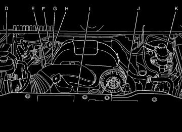
The main components of the instrument panel are the following:
A. Outlet Adjustment on page 3-30. B. Turn Signal/Multifunction Lever on page 3-7. C. Instrument Panel Cluster on page 3-35. D. Hazard Warning Flashers on page 3-6. E. Shift Lever. See Automatic Transmission Operation
on page 2-32.
F. Tow/Haul Mode on page 2-38 (If Equipped). G. Driver Information Center (DIC) on page 3-51. H. Audio System(s) on page 3-83. I. Exterior Lamps on page 3-14. J. Dome Lamp Override on page 3-19. Instrument
Panel Brightness on page 3-18. Fog Lamps on page 3-17 (If Equipped).
K. Hood Release on page 5-13. L. Integrated Trailer Brake Controller (If Equipped).
Towing a Trailer on page 4-50.
M. Automatic Transfer Case Control. (If Equipped). See
Four-Wheel Drive on page 2-40.
N. Cruise Control on page 3-12. O. Tilt Wheel on page 3-6. P. Horn on page 3-6. Q. Audio Steering Wheel Controls on page 3-138. R. Climate Control System on page 3-22 or Dual
Automatic Climate Control System on page 3-24
(If Equipped).S. Accessory Power Outlet(s) on page 3-20. Cigarette Lighter (If Equipped). See Ashtray(s) and Cigarette Lighter on page 3-21.
T. StabiliTrak® System on page 4-6 (If Equipped).
Pedal Adjust Button (If Equipped). See Adjustable Throttle and Brake Pedal on page 2-30. Ultrasonic Rear Parking Assist (URPA) on page 2-56
(If Equipped). Heated Windshield Washer Fluid Button (If Equipped). See Windshield Washer on page 3-10. Power Assist Steps on page 2-18
(If Equipped).U. Glove Box on page 2-78.
3-5
Tilt Wheel The vehicle has a tilt wheel that lets the steering wheel be adjusted.
Hazard Warning Flashers | (Hazard Warning Flasher): Press this button located on top of the steering column, to make the front and rear turn signal lamps flash on and off. This warns others that you are having trouble. Press again to turn the flashers off.
When the hazard warning flashers are on, the vehicle’s turn signals will not work.
Horn To sound the horn, press the center pad on the steering wheel.
The tilt steering wheel lever is located on the lower left side of the column. To tilt the wheel, hold the steering wheel and pull the lever. Then move the steering wheel to a comfortable position and release the lever to lock the wheel in place. Do not adjust the steering wheel while driving.
3-6
Turn Signal/Multifunction Lever
The lever on the left side of the steering column includes the following: G : Turn and Lane Change Signals 5 3 : Headlamp High/Low-Beam Changer N : Windshield Wipers L : Windshield Washer
5 : Rear Wiper Delay
Z : Rear Wiper = : Rear Wiper Wash Flash-to-Pass. Information for these features is on the pages following.
Turn and Lane-Change Signals
An arrow on the instrument panel cluster flashes in the direction of the turn or lane change.
Move the lever all the way up or down to signal a turn. Raise or lower the lever for less than one second until the arrow starts to flash to signal a lane change. This causes the turn signals to automatically flash three times. It will flash six times if tow-haul mode is active. Holding the turn signal lever for more than one second will cause the turn signals to flash until you release the lever. The lever returns to its starting position whenever it is released.
3-7
If after signaling a turn or a lane change the arrows flash rapidly or do not come on, a signal bulb could be burned out. Have the bulbs replaced. If the bulb is not burned out, check the fuse. See Fuses and Circuit Breakers on page 5-115. Turn Signal On Chime If the turn signal is left on for more than 3/4 of a mile (1.2 km), a chime will sound at each flash of the turn signal and the message TURN SIGNAL ON will also appear in the Driver Information Control (DIC). To turn the chime and message off, move the turn signal lever to the off position. Headlamp High/Low-Beam Changer 5 3 (Headlamp High/Low Beam Changer): To change the headlamps from low to high beam, push the lever toward the instrument panel. To return to low-beam headlamps, pull the multifunction lever toward you. Then release it.
When the high beams are on, this indicator light on the instrument panel cluster will also be on.
Flash-to-Pass This feature lets you use the high-beam headlamps to signal a driver in front of you that you want to pass. It works even if the headlamps are in the automatic position. To use it, pull the turn signal lever toward you, then release it. If the headlamps are in the automatic position or on low beam, the high-beam headlamps will turn on. They will stay on as long as you hold the lever toward you. The high-beam indicator on the instrument panel cluster will come on. Release the lever to return to normal operation.
3-8
Windshield Wipers Turn the band with the wiper symbol to control the windshield wipers. 8 (Mist): Turn to mist for a single wiping cycle. Hold it there until the wipers start. Then let go. The wipers stop after one wipe. Hold the band on mist longer, for more wipe cycles. 9 (Off): Turns the wipers off.
6 (Delay): Turn the band to adjust the delay time. The delay between wiping cycles becomes shorter as the band is moved to the top of the lever. This can be very useful in light rain or snow. 6 (Low Speed): For steady wiping at low speed.
? (High Speed): For high-speed wiping. Clear ice and snow from the wiper blades before using them. If they are frozen to the windshield, gently loosen or thaw them. Damaged wiper blades may not clear the windshield well, making it harder to see and drive safely. If the blades do become damaged, install new blades or blade inserts. For more information, see Windshield Wiper Blade Replacement on page 5-59.
Heavy snow or ice can overload the wiper motor. A circuit breaker will stop the motor until it cools down. Clear away snow or ice to prevent an overload.
Rainsense™ II Wipers For vehicles with Rainsense™ II windshield wipers, the moisture sensor is located next to the inside rearview mirror and is mounted on the windshield. When active, these sensors are able to detect moisture on the windshield and automatically turn on the wipers. To turn on the Rainsense feature, the wipers must be set to one of the five delay settings on the multifunction lever. Each of the five settings adjusts the sensitivity of the sensor. Since different drivers have different setting preferences, it is recommended that the mid-range setting (position 3) be used initially. For more wipes, select the higher settings; for fewer wipes, select the lower settings located closer to the off position on the multifunction lever. The sensor will automatically control the frequency of the wipes from the off setting to the high speed setting according to the weather conditions. The wipers can be left in a rainsense mode even when it is not raining.
3-9
When Rainsense is active, the headlamps will turn on automatically if the exterior lamp control is in the AUTO position and the wipers are active. Notice: Going through an automatic car wash with the wipers on can damage them. Turn the wipers off when going through an automatic car wash.
Windshield Washer
{ CAUTION:
In freezing weather, do not use your washer until the windshield is warmed. Otherwise the washer fluid can form ice on the windshield, blocking your vision.
L (Washer Fluid): Push the paddle marked with the windshield washer symbol at the top of the multifunction lever, to spray washer fluid on the windshield. The wipers clear the window and then either stop or return to the preset speed.
Heated Windshield Washer For vehicles with the heated windshield washer fluid system it can be used to help clear ice, snow, tree sap, or bugs from the windshield.
_ (Heated Washer Fluid): Press the heated washer fluid button to activate the heated windshield washer fluid system. This activation initiates four heated wash/wipe cycles. The first heated wash/wipe cycle may take up to 40 seconds to occur, depending on outside temperature. After the first wash/wipe cycle, it may take up to 20 seconds for each of the remaining cycles to begin. Press the button again to turn off the heated windshield washer fluid system or it will automatically turn off after four wipe cycles have been completed. When the heated windshield washer fluid system is activated under certain outside temperature conditions, steam may flow out of the washer nozzles for a short period of time before washer fluid is sprayed. This is a normal condition. HEATING WASH FLUID WASH WIPES PENDING is displayed on the DIC when the washer system is heating the fluid. WASHER FLUID LOW ADD FLUID is displayed when the washer fluid is low. See DIC Warnings and Messages on page 3-64.
3-10
Rear Window Wiper/Washer
{ CAUTION:
In freezing weather, do not use your washer until the windshield is warmed. Otherwise the washer fluid can form ice on the windshield, blocking your vision.
The rear wiper control is located on the turn signal/multifunction lever.
To turn the rear wiper on, slide the lever to a wiper position. 9 (Off): Turns the wiper off.
5 (Rear Wiper Delay): Turns on the rear wiper delay.
Z (Rear Wiper): Turns on the rear wiper. = (Rear Wiper Wash): To turn on the rear wiper wash, push the button on the end of the turn signal/multifunction lever to spray washer fluid on the rear window. The wipers will clear the rear window and either stop or return to your preset speed. For more washer cycles, press and hold the button. The rear window wiper/washer will not operate if the liftgate or liftglass is open or ajar. If the liftgate or liftglass is opened while the rear wiper is on, the wiper will return to the parked position and stop.
3-11
Cruise Control
{ CAUTION:
Cruise control can be dangerous where you cannot drive safely at a steady speed. So, do not use the cruise control on winding roads or in heavy traffic. Cruise control can be dangerous on slippery roads. On such roads, fast changes in tire traction can cause excessive wheel slip, and you could lose control. Do not use cruise control on slippery roads.
With cruise control, a speed of about 25 mph (40 km/h) or more can be maintained without keeping your foot on the accelerator. Cruise control does not work at speeds below about 25 mph (40 km/h). When the brakes are applied, cruise control is turned off. If the vehicle has StabiliTrak®, and the system begins to limit wheel spin, cruise control will automatically disengage. See StabiliTrak® System on page 4-6. When road conditions allow the cruise control to be safely used again, it can be turned back on.
3-12
The cruise control buttons are located on left side of the steering wheel. T (On/Off): This button can both activate and turn off the system. The indicator light on the button turns on when cruise control is on and turns off when cruise control is off.
+ RES (Resume/Accelerate): Press to make the vehicle accelerate or resume to a previously set speed. SET − (Set/Coast): Press to set the speed or make the vehicle decelerate.
[ (Cancel): Press to cancel cruise control without erasing the set speed from memory.
Setting Cruise Control Cruise control will not work if the parking brake is set, or if the master cylinder brake fluid level is low. The cruise control light on the instrument panel cluster comes on after the cruise control has been set to the desired speed.
{ CAUTION:
If you leave your cruise control on when you are not using cruise, you might hit a button and go into cruise when you do not want to. You could be startled and even lose control. Keep the cruise control switch off until you want to use cruise control.
1. Press the I button. 2. Get up to the desired speed. 3. Press the SET− button located on the steering
wheel and release it.
4. Take your foot off the accelerator.
Resuming a Set Speed If the cruise control is set at a desired speed and then the