- 2012 Chevrolet Suburban Owners Manuals
- Chevrolet Suburban Owners Manuals
- 2004 Chevrolet Suburban Owners Manuals
- Chevrolet Suburban Owners Manuals
- 1995 Chevrolet Suburban Owners Manuals
- Chevrolet Suburban Owners Manuals
- 1996 Chevrolet Suburban Owners Manuals
- Chevrolet Suburban Owners Manuals
- 2005 Chevrolet Suburban Owners Manuals
- Chevrolet Suburban Owners Manuals
- 2006 Chevrolet Suburban Owners Manuals
- Chevrolet Suburban Owners Manuals
- 2011 Chevrolet Suburban Owners Manuals
- Chevrolet Suburban Owners Manuals
- 1999 Chevrolet Suburban Owners Manuals
- Chevrolet Suburban Owners Manuals
- 1994 Chevrolet Suburban Owners Manuals
- Chevrolet Suburban Owners Manuals
- 1997 Chevrolet Suburban Owners Manuals
- Chevrolet Suburban Owners Manuals
- 2003 Chevrolet Suburban Owners Manuals
- Chevrolet Suburban Owners Manuals
- 2008 Chevrolet Suburban Owners Manuals
- Chevrolet Suburban Owners Manuals
- 2010 Chevrolet Suburban Owners Manuals
- Chevrolet Suburban Owners Manuals
- 2009 Chevrolet Suburban Owners Manuals
- Chevrolet Suburban Owners Manuals
- 2001 Chevrolet Suburban Owners Manuals
- Chevrolet Suburban Owners Manuals
- 2000 Chevrolet Suburban Owners Manuals
- Chevrolet Suburban Owners Manuals
- 1993 Chevrolet Suburban Owners Manuals
- Chevrolet Suburban Owners Manuals
- 2002 Chevrolet Suburban Owners Manuals
- Chevrolet Suburban Owners Manuals
- 2007 Chevrolet Suburban Owners Manuals
- Chevrolet Suburban Owners Manuals
- Download PDF Manual
-
works, then your vehicle needs service. B (ACCESSORY): This position lets you use things like the radio and the windshield wipers when the engine is off. Lengthy operation of features such as the radio in the ACCESSORY ignition position and the RUN position may drain the battery and prevent your vehicle from starting. Do not operate your vehicle in the ACCESSORY ignition position for a long period of time. C (RUN): This is the position for driving. It is the position the switch returns to after the engine starts, and you release the key. The battery could be drained if you leave the key in the ACCESSORY or RUN position with the engine off. You may not be able to start your vehicle if the battery is allowed to drain for an extended period of time. D (START): This position starts the engine.
Key In the Ignition Never leave your vehicle with the keys inside, as it is an easy target for joy riders or thieves. If you leave the key in the ignition and park your vehicle, a chime will sound, when you open the driver’s door. Always remember to remove your key from the ignition and take it with you. This will lock your ignition and transmission. Also, always remember to lock the doors. The battery could be drained if you leave the key in the ignition while your vehicle is parked. You may not be able to start your vehicle after it has been parked for an extended period of time.
Retained Accessory Power (RAP) Your vehicle has a Retained Accessory Power (RAP) feature which will allow certain features on your vehicle to continue to work up to 10 minutes after the ignition key is turned to LOCK. The radio, power windows, and if the vehicle has a sunroof and the OnStar® System, will work when the ignition key is in RUN or ACCESSORY. Once the key is turned from RUN to LOCK, the windows and sunroof will continue to work until a door is opened. The radio will continue to work for up to 10 minutes or until the driver’s door is opened.
Starting the Engine To place the transmission in the proper gear: Move your shift lever to PARK (P) or NEUTRAL (N). Your engine will not start in any other position -- this is a safety feature. To restart when you are already moving, use NEUTRAL (N) only. Starting Procedure 1. With your foot off the accelerator pedal, turn the ignition key to START. When the engine starts, let go of the key. The idle speed will go down as your engine gets warm. Do not race the engine immediately after starting it. Operate the engine and transmission gently to allow the oil to warm up and lubricate all moving parts. Your vehicle has a Computer-Controlled Cranking System. This feature assists in starting the engine and protects components. If the ignition key is turned to the START position, and then released when the engine begins cranking, the engine will continue cranking for a few seconds or until the vehicle starts.
141
If the engine does not start and the key is held in START for many seconds, cranking will be stopped after 15 seconds to prevent cranking motor damage. To prevent gear damage, this system also prevents cranking if the engine is already running. Engine cranking can be stopped by turning the ignition switch to the ACCESSORY or LOCK position.
Notice: Cranking the engine for long periods of time, by returning the key to the START position immediately after cranking has ended, can overheat and damage the cranking motor, and drain the battery. Wait at least 15 seconds between each try, to allow the cranking motor to cool down.
2. If the engine does not start after 5-10 seconds,
especially in very cold weather (below 0°F or −18°C), it could be flooded with too much gasoline. Try pushing the accelerator pedal all the way to the floor and holding it there as you hold the key in START for up to a maximum of 15 seconds. Wait at least 15 seconds between each try, to allow the cranking motor to cool down. When the engine starts, let go of the key and accelerator. If the vehicle starts briefly but then stops again, do the same thing. This clears the extra gasoline from the engine. Do not race the engine immediately after starting it. Operate the engine and transmission gently until the oil warms up and lubricates all moving parts.
Notice: Your engine is designed to work with the electronics in your vehicle. If you add electrical parts or accessories, you could change the way the engine operates. Before adding electrical equipment, check with your dealer. If you do not, your engine might not perform properly. Any resulting damage would not be covered by your vehicle’s warranty.
142
Adjustable Throttle and Brake Pedal If your vehicle has this feature, you can change the position of the throttle and brake pedals. This feature is designed for shorter drivers, since the pedals cannot move farther away from the standard position, but can move toward the driver for better pedal reach.
The switch used to adjust the pedals is located on the instrument panel below the climate control system.
Press the arrow at the bottom of the switch to move the pedals closer to your body. Press the arrow at the top of the switch to move the pedals away from your body.
No adjustment to the pedals can be made when the vehicle is in REVERSE (R) or while using the cruise control. Your vehicle may have a memory function which allows pedal settings to be saved and recalled. See Memory Seat, Mirrors, and Pedals on page 13
for more information. Engine Coolant Heater Your vehicle may have an engine coolant heater. In very cold weather, 0°F (−18°C) or colder, the engine coolant heater can help. You will get easier starting and better fuel economy during engine warm-up. Usually, the coolant heater should be plugged in a minimum of four hours prior to starting your vehicle. At temperatures above 32°F (0°C), use of the coolant heater is not required. Your vehicle may also have an internal thermostat in the plug end of the cord. This will prevent operation of the engine coolant heater when the temperature is at or above 0°F (−18°C) as noted on the cord.143
4. Before starting the engine, be sure to unplug and store the cord as it was before to keep it away from moving engine parts. If you do not, it could be damaged.
How long should you keep the coolant heater plugged in? The answer depends on the outside temperature, the kind of oil you have, and some other things. Instead of trying to list everything here, we ask that you contact your dealer in the area where you will be parking your vehicle. The dealer can give you the best advice for that particular area.
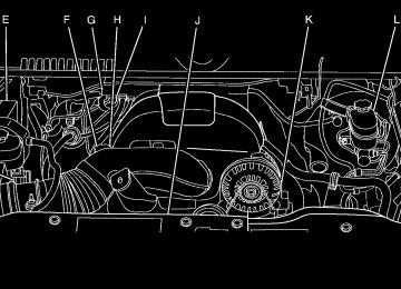
To Use the Engine Coolant Heater 1. Turn off the engine. 2. Open the hood and unwrap the electrical cord. The cord is located on the driver’s side of the engine compartment, near the power steering fluid reservoir.
3. Plug the cord into a normal, grounded
110-volt AC outlet.
{CAUTION:
Plugging the cord into an ungrounded outlet could cause an electrical shock. Also, the wrong kind of extension cord could overheat and cause a fire. You could be seriously injured. Plug the cord into a properly grounded three-prong 110-volt AC outlet. If the cord will not reach, use a heavy-duty three-prong extension cord rated for at least 15 amps.
144
Active Fuel Management™ Your vehicle’s V8 engine may have Active Fuel Management™. This system allows the engine to operate on either all or half of its cylinders, depending on the driving conditions. When less power is required, such as cruising at a constant vehicle speed, the system will operate in the half cylinder mode, allowing your vehicle to achieve better fuel economy. When greater power demands are required, such as accelerating from a stop, passing, or merging onto a freeway, the system will maintain full-cylinder operation. Your vehicle has an Active Fuel Management™ indicator. For more information on using this display see DIC Operation and Displays (With DIC Buttons) on page 261 or DIC Operation and Displays (Without DIC Buttons) on page 267.
Automatic Transmission Operation There are several different positions for the shift lever.
Your vehicle has an automatic transmission with an electronic shift position indicator within the instrument panel cluster. This display will show the position anytime the shift lever is moved out of PARK (P).
145
PARK (P): This position locks your rear wheels. It is the best position to use when you start your engine because your vehicle cannot move easily.
{CAUTION:
{CAUTION:
It is dangerous to get out of your vehicle if the shift lever is not fully in PARK (P) with the parking brake firmly set. Your vehicle can roll. Do not leave your vehicle when the engine is running unless you have to. If you have left the engine running, the vehicle can move suddenly. You or others could be injured. To be sure your vehicle will not move, even when you are on fairly level ground, always set your parking brake and move the shift lever to PARK (P). See Shifting Into Park (P) on page 157. If you are pulling a trailer, see Towing a Trailer on page 422.
If you have four-wheel drive, your vehicle will be free to roll — even if your shift lever is in PARK (P) — if your transfer case is in NEUTRAL. So, be sure the transfer case is in a drive gear, two-wheel high, four-wheel high or four-wheel low — not in NEUTRAL. See Shifting Into Park (P) on page 157.
REVERSE (R): Use this gear to back up. Notice: Shifting to REVERSE (R) while your vehicle is moving forward could damage the transmission. The repairs would not be covered by your warranty. Shift to REVERSE (R) only after your vehicle is stopped. To rock your vehicle back and forth to get out of snow, ice, or sand without damaging your transmission, see If Your Vehicle is Stuck in Sand, Mud, Ice, or Snow on page 404.
146
NEUTRAL (N): In this position, your engine does not connect with the wheels. To restart when you are already moving, use NEUTRAL (N) only. Also, use NEUTRAL (N) when your two-wheel drive vehicle is being towed.
{CAUTION:
Shifting into a drive gear while your engine is running at high speed is dangerous. Unless your foot is firmly on the brake pedal, your vehicle could move very rapidly. You could lose control and hit people or objects. Do not shift into a drive gear while your engine is running at high speed.
Notice: Shifting out of PARK (P) or NEUTRAL (N) with the engine running at high speed may damage the transmission. The repairs would not be covered by your warranty. Be sure the engine is not running at high speed when shifting your vehicle.
DRIVE (D): This position is for normal driving. It provides the best fuel economy for your vehicle. If you need more power for passing, and you are: (cid:129) Going less than about 35 mph (56 km/h), push
your accelerator pedal about halfway down.
(cid:129) Going about 35 mph (56 km/h) or more, push
the accelerator all the way down.
DRIVE (D) can be used when towing a trailer, carrying a heavy load, driving on steep hills or for off-road driving. You may want to shift the transmission to THIRD (3) or, if necessary, a lower gear selection if the transmission shifts too often. Downshifting the transmission in slippery road conditions could result in skidding, see “Skidding” under Loss of Control on page 371
THIRD (3): This position is also used for normal driving. However, it reduces vehicle speed more than DRIVE (D) without using your brakes. You can use THIRD (3) on hills. It can help control your speed as you go down steep mountain roads, but then you would also want to use your brakes off and on.
147
Notice: Spinning the tires or holding the vehicle in one place on a hill using only the accelerator pedal may damage the transmission. The repair will not be covered by your warranty. If you are stuck, do not spin the tires. When stopping on a hill, use the brakes to hold the vehicle in place. When temperatures are very cold, the Hydra-Matic® Automatic Transmission’s gear shifting may be delayed providing more stable shifts until the engine warms up. Shifts may be more noticeable with a cold transmission. This difference in shifting is normal. The transmission torque converter clutch operation is restricted during cold operation. When the startup transmission temperature is approximately 64°F (18°C) your torque converter clutch will temporarily not operate. Once the transmission temperature rises above 68°F (20°C), normal operation will resume.
SECOND (2): This position reduces vehicle speed even more than THIRD (3) without using your brakes. You can use SECOND (2) on hills. It can help control your speed as you go down steep mountain roads, but then you would also want to use your brakes off and on. If you select SECOND (2) and the Tow/Haul has not been selected, the transmission will drive in SECOND (2) gear. You may use this feature for reducing the speed of the rear wheels when you are trying to start your vehicle from a stop on slippery road surfaces. If you select SECOND (2) and the Tow/Haul has also been selected, the transmission operation will be limited to FIRST (1) and SECOND (2) gears. You may use this feature for reducing the speed of the rear wheels when you are trying to start your vehicle from a stop on slippery road surfaces.
FIRST (1): This position reduces vehicle speed even more than SECOND (2) without using your brakes. You can use it on very steep hills, or in deep snow or mud. If the shift lever is put in FIRST (1) while the vehicle is moving forward, the transmission will not shift into first gear until the vehicle is going slowly enough.
148
Tow/Haul Mode
When Tow/Haul mode is selected the Tow/Haul indicator light will come on.
The Tow/Haul mode works with the Autoride® feature, if the vehicle has this, to enhance the ride when trailering or with a loaded vehicle. See Autoride® on page 422.
Your vehicle has a Tow/Haul mode. The selector button is located on the end of the column shift lever. You can use this feature to assist when towing or hauling a heavy load or if there is a need to charge a battery installed in a trailer. See Towing a Trailer on page 422 for more information.
149
Automatic Transfer Case
The transfer case knob is located to the left of the instrument panel cluster.
Your vehicle has Four Wheel Drive with StabiliTrak®. For information on StabiliTrak®, see StabiliTrak® System on page 363. Use this dial to shift into and out of four-wheel drive.
Four-Wheel Drive If your vehicle has four-wheel drive, you can send your engine’s driving power to all four wheels for extra traction. Read the part that follows before using four-wheel drive. Notice: Driving on clean, dry pavement in Four-Wheel-Drive High or Four-Wheel-Drive Low for an extended period of time may cause premature wear on your vehicle’s powertrain. Do not drive on clean, dry pavement in Four-Wheel-Drive High or Four-Wheel-Drive Low for extended periods of time. While driving on clean dry pavement and during tight turns, you may experience a vibration in the steering system. Front Axle Locking Feature The front axle locks and unlocks automatically when you shift the transfer case. Some delay for the axle to lock or unlock is normal.
150
You can choose among five driving settings: Indicator lights in the switches show you which setting you are in. The indicator lights will come on briefly when you turn on the ignition and the last chosen setting will stay on. If the lights do not come on, you should take your vehicle in for service. An indicator light will flash while shifting. Fast flashing means the conditions were not met to make the desired shift, typically the vehicle was going too fast, the automatic transmission was not in neutral, or the clutch pedal was not fully pressed. Slow flashing means the shift is in progress. It will stay on when the shift is completed. If for some reason the transfer case cannot make a requested shift, it will return to the last chosen setting. 2 m (Two-Wheel Drive High): This setting is used for driving in most street and highway situations. Your front axle is not engaged in two-wheel drive. This setting also provides the best fuel economy.
AUTO (Automatic Four-Wheel Drive): This setting is ideal for use when road surface traction conditions are variable. When driving your vehicle in AUTO, the front axle is engaged, but the vehicle’s power is primarily sent to the rear wheels. When the vehicle’s software determines a need for more traction, the system will transfer more power to the front wheels. Driving in this mode results in slightly lower fuel economy than Two-Wheel Drive High. 4 m (Four-Wheel Drive High): Use the four-wheel high position when you need extra traction, such as on snowy or icy roads or in most off-road situations. This setting also engages your front axle to help drive your vehicle. This is the best setting to use when plowing snow.
151
4 n (Four-Wheel Drive Low): This setting also engages your front axle and delivers extra torque. You may never need this setting. It sends maximum power to all four wheels. You might choose Four-Wheel Drive Low if you are driving off-road in deep sand, deep mud, deep snow, and while climbing or descending steep hills. StabiliTrak® will not engage in this mode. See StabiliTrak® System on page 363 for more information.
{CAUTION:
Shifting the transfer case to NEUTRAL can cause your vehicle to roll even if the transmission is in PARK (P). You or someone else could be seriously injured. Be sure to set the parking brake before placing the transfer case in NEUTRAL. See Parking Brake on page 156.
NEUTRAL (N): Shift the vehicle’s transfer case to NEUTRAL only when towing your vehicle. See Recreational Vehicle Towing on page 418 or Towing Your Vehicle on page 417 for more information. If the SERVICE 4 WHEEL DRIVE message stays on, you should take your vehicle to your dealer for service. See “SERVICE 4 WHEEL DRIVE message” under DIC Warnings and Messages on page 270. Shifting Into Four-Wheel Drive High or AUTO (Automatic Four-Wheel Drive) Turn the knob to the Four-Wheel High or AUTO position. This can be done at any speed, except when shifting from Four-Wheel Drive Low. The indicator light will flash while shifting. It will remain on when the shift is completed.
152
Shifting Into Two-Wheel Drive High Turn the knob to the Two-Wheel High position. This can be done at any speed, except when shifting from Four-Wheel Drive Low. See shifting out of Four-Wheel Drive Low later in this section for more information. Shifting Into Four-Wheel Drive Low When Four-Wheel Low is engaged, vehicle speed should be kept below 45 mph. Extended high-speed operation in 4L may damage or shorten the life of the drivetrain. To shift to the Four-Wheel Drive Low position, the ignition must be in RUN and the vehicle must be stopped or moving less than 3 mph (5 km/h) with the transmission in NEUTRAL (N). The preferred method for shifting into Four-Wheel Drive Low is to have your vehicle moving 1 to 2 mph (1.6 to 3.2 km/h). Turn the knob to the Four-Wheel Drive Low position. You must wait for the Four-Wheel Drive Low indicator light to stop flashing and remain on before shifting your transmission in gear.
Notice: Shifting the transmission into gear before the Four-Wheel Drive Low indicator light has stopped flashing could damage the transfer case. To help avoid damaging your vehicle, always wait for the Four-Wheel Drive Low indicator light to stop flashing before shifting the transmission into gear. The vehicle may have significant engagement noise and bump when shifting between Four-Wheel Drive Low and Four-Wheel Drive High ranges or from NEUTRAL while the engine is running. If the knob is turned to the Four-Wheel Drive Low position when your vehicle is in gear and/or moving, the Four-Wheel Drive Low indicator light will flash for 30 seconds and not complete the shift unless your vehicle is moving less than 3 mph (5 km/h) and the transmission is in NEUTRAL (N). After 30 seconds the transfer case will shift to Four-Wheel Drive High mode.
153
Shifting Out of Four-Wheel Drive Low To shift from Four-Wheel Drive Low to Four-Wheel Drive High, AUTO, or Two-Wheel Drive High, your vehicle must be stopped or moving less than 3 mph (5 km/h) with the transmission in NEUTRAL (N) and the ignition in RUN. The preferred method for shifting out of Four-Wheel Drive Low is to have your vehicle moving 1 to 2 mph (1.6 to 3.2 km/h). Turn the knob to the Four-Wheel Drive High, AUTO, or Two-Wheel Drive High position. You must wait for the Four-Wheel Drive High, AUTO, or Two-Wheel Drive High indicator light to stop flashing and remain on before shifting your transmission into gear. Notice: Shifting the transmission into gear before the Four-Wheel Drive Low indicator light has stopped flashing could damage the transfer case. To help avoid damaging your vehicle, always wait for the Four-Wheel Drive Low indicator light to stop flashing before shifting the transmission into gear. The vehicle may have significant engagement noise and bump when shifting between Four-Wheel Drive Low and Four-Wheel Drive High ranges or from NEUTRAL while the engine is running.
154
If the knob is turned to the Four-Wheel Drive High, AUTO, or Two-Wheel Drive High switch position when your vehicle is in gear and/or moving, the Four-Wheel Drive High, AUTO or Two-Wheel Drive High indicator light will flash for 30 seconds but will not complete the shift unless your vehicle is moving less than 3 mph (5 km/h) and the transmission is in NEUTRAL (N). Shifting into NEUTRAL To shift the transfer case to NEUTRAL do the following:
1. Make sure the vehicle is parked so that it will
not roll.
2. Set the parking brake and apply the regular
brake pedal. See Parking Brake on page 156
for more information.3. Start the vehicle or turn the ignition to RUN. 4. Put the transmission in NEUTRAL (N). 5. Shift the transfer case to Two-Wheel
Drive High.
6. Turn the transfer case dial clockwise to
NEUTRAL till it stops and hold it for 10 seconds. Then slowly release the dial to the four low position. The NEUTRAL light will come on when the transfer case shift to NEUTRAL is complete.
7. If the engine is running, verify that the
transmission is in NEUTRAL (N) by shifting the transmission to REVERSE (R) for one second, then shift the transmission to DRIVE (D) for one second.
8. Turn the ignition to ACCESSORY, which will
turn the engine off.
9. Place the transmission shift lever in PARK (P). 10. Release the parking brake prior to moving
the vehicle.
11. Turn the ignition to LOCK. Shifting Out of NEUTRAL To shift out of NEUTRAL do the following: 1. Set the parking brake and apply the regular
brake pedal.
2. Shift the transmission to NEUTRAL (N) and turn the ignition to RUN with the engine off.
3. Turn the transfer case dial to the desired
transfer case shift position (Two-Wheel Drive High, Four-Wheel Drive High, AUTO). After the transfer case has shifted out of NEUTRAL the NEUTRAL light will go out.
4. Release the parking brake prior to moving the
vehicle.
Notice: Shifting the transmission into gear before the Four-Wheel Drive Low indicator light has stopped flashing could damage the transfer case. To help avoid damaging your vehicle, always wait for the Four-Wheel Drive Low indicator light to stop flashing before shifting the transmission into gear. 5. Start the engine and shift the transmission to
the desired position.
Excessively shifting the transfer case into or out of the different modes may cause the transfer case to enter the shift protection mode. This will protect the transfer case from possible damage and will only allow the transfer case to respond to one shift per 10 seconds. The transfer case may stay in this mode for up to three minutes.
155
Parking Brake To set the parking brake, hold the regular brake pedal down with your right foot. Push down the parking brake pedal with your left foot. A chime will activate and the warning light will flash when the parking brake is applied and the vehicle is moving at least 5 mph (8 km/h).
To release the parking brake, hold the regular brake pedal down. Pull the bottom edge of the lever, located above the parking brake pedal, with the parking brake symbol, to release the parking brake. If the ignition is on when the parking brake is released, the brake system warning light will go off. Notice: Driving with the parking brake on can overheat the brake system and cause premature wear or damage to brake system parts. Verify that the parking brake is fully released and the brake warning light is off before driving. If you are towing a trailer and are parking on any hill, see Towing a Trailer on page 422.
156
Shifting Into Park (P)
{CAUTION:
1. Hold the brake pedal down with your right foot
and set the parking brake.
2. Move the shift lever into the PARK (P)
position by pulling the shift lever toward you and moving it up as far as it will go.
3. Be sure the transfer case is in a drive
gear — not in NEUTRAL (N). 4. Turn the ignition key to LOCK. 5. Remove the key and take it with you. If you
can leave your vehicle with the ignition key in your hand, your vehicle is in PARK (P).
It can be dangerous to get out of your vehicle if the shift lever is not fully in PARK (P) with the parking brake firmly set. Your vehicle can roll. If you have left the engine running, the vehicle can move suddenly. You or others could be injured. To be sure your vehicle will not move, even when you are on fairly level ground, use the steps that follow. With four-wheel drive, if your transfer case is in NEUTRAL, your vehicle will be free to roll, even if your shift lever is in PARK (P). So, be sure the transfer case is in a drive gear — not in NEUTRAL. If you are pulling a trailer, see Towing a Trailer on page 422.
157
Leaving Your Vehicle With the Engine Running
{CAUTION:
It can be dangerous to leave your vehicle with the engine running. Your vehicle could move suddenly if the shift lever is not fully in PARK (P) with the parking brake firmly set. If you have four-wheel drive and your transfer case is in NEUTRAL, your vehicle will be free to roll, even if your shift lever is in PARK (P). So be sure the transfer case is in a drive gear — not in NEUTRAL. And, if you leave the vehicle with the engine running, it could overheat and even catch fire. You or others could be injured. Do not leave your vehicle with the engine running unless you have to.
If you have to leave your vehicle with the engine running, be sure your vehicle is in PARK (P) and the parking brake is firmly set before you leave it. After you move the shift lever into PARK (P), hold the regular brake pedal down. Then, see if you can move the shift lever away from PARK (P) without first pulling it toward you. If you can, it means that the shift lever was not fully locked into PARK (P). Torque Lock If you are parking on a hill and you do not shift your transmission into PARK (P) properly, the weight of the vehicle may put too much force on the parking pawl in the transmission. You may find it difficult to pull the shift lever out of PARK (P). This is called torque lock. To prevent torque lock, set the parking brake and then shift into PARK (P) properly before you leave the driver’s seat. To find out how, see Shifting Into Park (P) on page 157. When you are ready to drive, move the shift lever out of PARK (P) before you release the parking brake.
158
If torque lock does occur, you may need to have another vehicle push yours a little uphill to take some of the pressure from the parking pawl in the transmission, then you will be able to pull the shift lever out of PARK (P).
Shifting Out of Park (P) Your vehicle has an automatic transmission shift lock control system which locks the shift lever in PARK (P) when the ignition is in the LOCK. You have to fully apply your regular brakes before you can shift from PARK (P) when the ignition is in RUN. See Automatic Transmission Operation on page 145. If you cannot shift out of PARK (P), ease pressure on the shift lever and push the shift lever all the way up into PARK (P) as you maintain brake application. Move the shift lever into another gear.
Parking Over Things That Burn
{CAUTION:
Things that can burn could touch hot exhaust parts under your vehicle and ignite. Do not park over papers, leaves, dry grass, or other things that can burn.
159
CAUTION:
(Continued)
(cid:129) Your vehicle was damaged when
driving over high points on the road or over road debris.
(cid:129) Repairs were not done correctly. (cid:129) Your vehicle or the exhaust system
has been modified improperly.
If you ever suspect exhaust is coming into your vehicle:
(cid:129) Drive it only with all the windows
down to blow out any CO; and
(cid:129) Have your vehicle fixed immediately.
Engine Exhaust
{CAUTION:
Engine exhaust can kill. It contains the gas carbon monoxide (CO), which you cannot see or smell. It can cause unconsciousness and death. You might have exhaust coming in if:
(cid:129) The exhaust system sounds strange
or different.
(cid:129) Your vehicle gets rusty underneath. (cid:129) Your vehicle was damaged in a
collision.
CAUTION:
(Continued)
160
Running the Engine While Parked It is better not to park with the engine running. But if you ever have to, here are some things to know.
{CAUTION:
Idling the engine with the climate control system off could allow dangerous exhaust into your vehicle. See the earlier caution under Engine Exhaust on page 160. Also, idling in a closed-in place can let deadly carbon monoxide (CO) into your vehicle even if the climate control fan is at the highest setting. One place this can happen is a garage. Exhaust — with CO — can come in easily. NEVER park in a garage with the engine running. Another closed-in place can be a blizzard. See Winter Driving on page 400.
{CAUTION:
It can be dangerous to get out of your vehicle if the shift lever is not fully in PARK (P) with the parking brake firmly set. Your vehicle can roll. Do not leave your vehicle when the engine is running unless you have to. If you have left the engine running, the vehicle can move suddenly. You or others could be injured. To be sure your vehicle will not move, even when you are on fairly level ground, always set the parking brake and move the shift lever to PARK (P).
161
{CAUTION:
Four-wheel drive vehicles with the transfer case in NEUTRAL will allow the vehicle to roll, even if the shift lever is in PARK (P). So, be sure the transfer case is in a drive gear — not in NEUTRAL. Always set the parking brake.
Follow the proper steps to be sure your vehicle will not move. See Shifting Into Park (P) on page 157. If you are pulling a trailer, see Towing a Trailer on page 422.
Mirrors
Automatic Dimming Rearview Mirror with OnStar®, Compass and Temperature Display Your vehicle may have this feature. When on, the automatic dimming mirror dims to the proper level to minimize glare from lights behind you after dark. The mirror has a dual display in the upper right corner of the mirror face that shows the compass reading and the outside temperature. Control buttons for the OnStar® system are at the bottom of the mirror. See OnStar® System on page 173 for more information about the services OnStar® provides. P(On/Off): This is the on/off button.
162
Temperature and Compass Display Press the on/off button, located to the far left, briefly to turn the compass/temperature display on or off. If the display reads CAL, the compass needs to be calibrated. For more information, see “Compass Calibration” following. To adjust between Fahrenheit and Celsius, do the following: 1. Press and hold the on/off button for
approximately four seconds until either a flashing F or C appears.
2. Press the button again to change the display
to the desired unit of measurement. After approximately four seconds of inactivity, the new unit will be locked in and the compass/temperature display will return.
If an abnormal temperature reading is displayed for an extended period of time, see your dealer. Under certain circumstances, a delay in updating the temperature is normal.
Automatic Dimming Mirror Operation The automatic dimming mirror function is turned on automatically each time the ignition is started. To operate the automatic dimming mirror, do the following: 1. Make sure the green indicator light, located to
the left of the on/off button, is lit. If it is not, press and hold the on/off button for approximately six seconds until the green light comes on, indicating that the mirror is in automatic dimming mode.
2. Turn off the automatic dimming mirror function
by pressing and holding the on/off button for approximately six seconds, until the green indicator light turns off.
163
Compass Variance The mirror is set in zone eight upon leaving the factory. It will be necessary to adjust the compass to compensate for compass variance if the vehicle is outside of zone eight. Under certain circumstances, as during a long distance cross-country trip, it will be necessary to adjust for compass variance. Compass variance is the difference between earth’s magnetic north and true geographic north. If not adjusted to account for compass variance, the compass could give false readings.
Compass Calibration The compass may need calibration if one of the following occurs: (cid:129) After approximately five seconds, the display
does not show a compass heading, N for North, for example, there may be a strong magnetic field interfering with the compass. Such interference may be caused by a magnetic antenna mount, magnetic note pad holder, or a similar magnetic item.
(cid:129) The compass does not display the correct heading and the compass zone variance is set correctly.
In order to calibrate, CAL must be displayed in the mirror compass windows. If CAL is not displayed, push the on/off button for approximately 12 seconds or until CAL is displayed. The compass can be calibrated by driving the vehicle in circles at 5 mph (8 km/h) or less until the display reads a direction.
164
To adjust for compass variance, do the following: 1. Find your current location and variance
zone number on the following zone map.
3. Keep pressing the on/off button until the
desired zone number appears in the display. Release the button. After approximately four seconds of inactivity, the new zone number will be locked in and the compass/temperature display will return.
Cleaning the Mirror When cleaning the mirror, use a paper towel or similar material dampened with glass cleaner. Do not spray glass cleaner directly on the mirror as that may cause the liquid cleaner to enter the mirror housing.
2. Press and hold the on/off button until a Z and
a zone number appears in the display. The compass is now in zone mode.
165
Automatic Dimming Rearview Mirror with Compass and Temperature Display Your vehicle may have this mirror. When on, an automatic dimming mirror will dim to the proper level to minimize glare from lights behind you after dark. The mirror also includes a dual display in the upper right corner of the mirror with the compass reading and the outside temperature. Yb: Briefly press this button to turn the display on or off.
Temperature Display The temperature can be displayed by pressing the compass/temperature button. Pressing the compass/temperature button once briefly, will toggle the display reading on and off. To alternate the temperature reading between Fahrenheit and Celsius, press and hold the compass/temperature button for approximately three seconds until the display blinks F and C. After approximately five seconds of inactivity, the display will stop blinking and display the last selection made. If an abnormal reading is displayed, see your dealer.
166
Automatic Dimming Mirror Operation O: Press this button to turn the automatic dimming feature on or off. The indicator light to the left of the button will turn on to indicate when the feature is on. Once the mirror is turned off, it will remain off until it is turned back on, or until the vehicle is restarted. Compass Operation Press the compass/temperature button once briefly to turn the display on or off. Compass Calibration The compass may need calibration if one of the following occurs:
If CAL is displayed while driving in the vehicle.
(cid:129) After approximately five seconds, the display
does not show a compass heading, N for North, for example, there may be a strong magnetic field interfering with the compass. Such interference may be caused by a magnetic antenna mount, magnetic note pad holder, or a similar magnetic item.
(cid:129) The compass does not display the correct heading and the compass zone variance is set correctly.
In order to calibrate, CAL must be displayed in the mirror compass windows. If CAL is not displayed, push in the compass/temperature button for approximately nine seconds or until CAL is displayed. The compass can be calibrated by driving the vehicle in circles at 5 mph (8 km/h) or less until the display reads a direction. Compass Variance The mirror is set in zone eight upon leaving the factory. It will be necessary to adjust the compass to compensate for compass variance if the vehicle is outside zone eight. Under certain circumstances, as during a long distance cross-country trip, it will be necessary to adjust for compass variance. Compass variance is the difference between earth’s magnetic north and true geographic north. If not adjusted to account for compass variance, your compass could give false readings.
167
(cid:129) 3. Press the compass/temperature button on the
bottom of the mirror until the new zone number appears in the display. After you stop pressing the button, the display will show a compass direction within a few seconds.
Cleaning the Mirror Use a paper towel or similar material dampened with glass cleaner. Do not spray glass cleaner directly on the mirror as that may cause the liquid cleaner to enter the mirror housing.
Outside Manual Mirrors Adjust your outside mirrors so you can just see the side of your vehicle and have a clear view of objects behind you. The mirrors can be folded in to enter narrow areas. The use of hood-mounted air deflectors and add-on convex mirror attachments may adversely affect mirror performance.
To adjust for compass variance: 1. Find your current location and variance zone
number on the following zone map.
2. Press and hold the compass/temperature
button for six seconds until a zone number appears in the display.
168
Outside Trailer-Tow Mirrors
If your vehicle has trailer towing type mirrors, they can be adjusted so you can have a clear view of the objects behind you. Manually pull out the mirror head to extend it for better visibility when towing a trailer.
These mirrors can be manually folded forward or rearward. The lower portion of the mirror is convex. A convex mirror’s surface is curved so you can see more from the driver’s seat. The convex mirror can be adjusted manually to the driver’s preferred position for better vision. Your vehicle may have outside heated mirrors which help clear them of condensation, snow, and ice. When the rear window defogger button is pressed, the heated mirrors are also turned on. Only the upper glass of the mirror is heated. The lower convex part of the mirror is not heated. Your mirror may also have a turn signal arrow that will flash in the direction of the turn or lane change.
169
Outside Power Mirrors
If your vehicle is equipped with outside power mirrors, the controls are located on the driver’s door armrest.
Press (A) to select the driver’s side mirror or (B) to select the passenger’s side mirror. Press either (A) or (B) again to deselect the mirror.
To adjust each mirror, press one of the four arrows located on the control pad to move the mirror in the direction you want it to go. Adjust each outside mirror so that you can see a little of your vehicle, and the area behind your vehicle. The mirrors may also include a memory function that works with the memory seats. See Memory Seat, Mirrors, and Pedals on page 13 for more information. The mirrors can be manually folded inward to prevent damage when going through an automatic car wash. To fold, push the mirror toward the vehicle. To return the mirror to its original position, push outward. Be sure to return both mirrors to their original unfolded position before driving.
170
Outside Power Foldaway Mirrors
If your vehicle is equipped with outside power foldaway mirrors, the controls are located on the driver’s door armrest.
(cid:129) Press (A) to select the driver’s side mirror. Then
press the arrows located on the four-way control pad to adjust the mirror. Press (A) again to deselect this mirror.
(cid:129) Press (B) to select the passenger’s side mirror. Then press the arrows located on the four-way control pad to adjust the mirror. Press (B) again to deselect this mirror.
(cid:129) Press (C), to fold the mirrors out to the driving
(cid:129) Press (D) to fold the mirrors in to the folded
position.
position.
If the mirrors are accidentally folded/unfolded manually, they may shake or flutter at normal driving speeds and may not stay in the unfolded position. If this happens, you will need to reset the mirrors. See “Resetting the Power Foldaway Mirrors” next. Resetting the Power Foldaway Mirrors You will need to reset the power foldaway mirrors if the following occurs: (cid:129) The mirrors are accidentally obstructed while
folding.
(cid:129) They are accidentally manually
folded/unfolded.
(cid:129) The mirrors will not stay in the unfolded
position.
(cid:129) The mirrors shake and flutter at normal driving
speeds.
To reset the power foldaway mirrors, fold and unfold them one time using the mirror controls. This will reset them to their normal position.
171
Turn Signal Indicator Your vehicle may have a turn signal indicator on the mirror. An arrow on the mirror will flash in the direction of the turn or lane change. Ground Illumination Lamps The mirrors may also include ground illumination lamps in the base of the mirror. These lamps help you see the area near the base of the front doors when it is dark out. Outside Automatic Dimming Mirror If your vehicle is equipped with this feature, the driver’s outside mirror will adjust for the glare of headlamps behind you. This feature is controlled by the on and off settings found on the electrochromic inside mirror. See Automatic Dimming Rearview Mirror with OnStar®, Compass and Temperature Display on page 162 or Automatic Dimming Rearview Mirror with Compass and Temperature Display on page 166 for more information.
Outside Curb View Assist Mirrors If your vehicle has the memory package, the outside mirrors are able to perform the curb view assist mirror function. This feature may be useful in in allowing the driver to view the curb when parallel parking. This feature will cause the passenger’s and/or driver’s mirror to tilt to a preselected position when the vehicle is in REVERSE (R). The passenger’s and/or driver’s mirror will return to its original position when the vehicle is shifted out of REVERSE (R) and either a thirty second delay has occurred, the vehicle speed is greater than 8 mph (12 km/h), or the ignition is turned to off. This feature can be turned on or off through the Driver Information Center (DIC). See Driver Information Center (DIC) on page 260 for more information.
172
Outside Convex Mirror Your passenger’s side mirror may have convex glass. A convex mirror’s surface is curved so you can see more from the driver’s seat.
{CAUTION:
A convex mirror can make things (like other vehicles) look farther away than they really are. If you cut too sharply into the right lane, you could hit a vehicle on your right. Check your inside mirror or glance over your shoulder before changing lanes.
Outside Heated Mirrors The vehicle may have outside heated mirrors which help clear them of condensation, snow, and ice. When the rear window defogger button is pressed, the heated mirrors are also turned on. See “Rear Window Defogger” under Dual Automatic Climate Control System on page 231 or Climate Control System on page 227 for more information.
OnStar® System
OnStar® uses several innovative technologies and live advisors to provide you with a wide range of safety, security, information, and convenience services. If your airbags deploy, the system is designed to make an automatic call to OnStar® Emergency advisors who can request emergency services be sent to your location. If you lock your keys in the vehicle, call OnStar® at 1-888-4-ONSTAR and they can send a signal to unlock your doors. If you need roadside assistance, press the OnStar® button and they can contact Roadside Service for you.
173
OnStar® service is provided to you subject to the OnStar® Terms and Conditions. You may cancel your OnStar® service at any time by contacting OnStar® as provided below. A complete OnStar® Owners Guide and the OnStar® Terms and Conditions are included in the vehicle’s OnStar® Subscriber glove box literature. For more information, visit onstar.com or onstar.ca, contact OnStar® at 1-888-4-ONSTAR (1-888-466-7827) or TTY 1-877-248-2080, or press the OnStar® button to speak with an OnStar® advisor 24 hours a day, 7 days a week. Not all OnStar® features are available on all vehicles. To check if your vehicle is equipped to provide the services described below, or for a full description of OnStar® services and system limitations, see the OnStar® Owner’s Guide in your glove box or visit onstar.com. OnStar® Services For new vehicles with OnStar®, the Safe & Sound Plan, or the Directions & Connections® Plan is included for one year from the date of purchase. You can extend this plan beyond the first year, or upgrade to the Directions & Connections® Plan.
174
For more information, press the OnStar® button to speak with an advisor. Some OnStar® services (such as Remote Door Unlock or Stolen Vehicle Location Assistance) may not be available until you register with OnStar®. Available Services with Safe & Sound® Plan (cid:129) Automatic Notification of Airbag Deployment (cid:129) Advanced Automatic Crash Notification (AACN)
(If equipped) Link to Emergency Services
(cid:129) Roadside Assistance (cid:129) Stolen Vehicle Location Assistance (cid:129) AccidentAssist (cid:129) Remote Door Unlock/Vehicle Alert (cid:129) OnStar® Vehicle Diagnostics (cid:129) GM Goodwrench® On Demand Diagnostics (cid:129) OnStar® Hands-Free Calling with
30 complimentary minutes
(cid:129) OnStar® Virtual Advisor (U.S. Only)
(cid:129) Available Services included with Directions & Connections® Plan (cid:129) All Safe and Sound Plan Services (cid:129) Driving Directions - Advisor delivered or
OnStar® Turn-by-Turn Navigation (If equipped)
(cid:129) RideAssist
Information and Convenience Services
OnStar® Hands-Free Calling OnStar® Hands-Free Calling allows eligible OnStar® subscribers to make and receive calls using voice commands. Hands-Free Calling is fully integrated into the vehicle, and can be used with OnStar® Pre-Paid Minute Packages. Hands-Free Calling may also be linked to a Verizon Wireless service plan in the U.S. or a Bell Mobility service plan in Canada, depending on eligibility. To find out more, refer to the OnStar® Owners Guide in the vehicle’s glove box, visit www.onstar.com or www.onstar.ca, or speak with an OnStar® advisor by pressing the OnStar® button or calling 1-888-4-ONSTAR (1-888-466-7827).
OnStar® Virtual Advisor OnStar® Virtual Advisor is a feature of OnStar® Hands-Free Calling that uses your minutes to access location-based weather, local traffic reports, and stock quotes. By pressing the phone button and giving a few simple voice commands, you can browse through the various topics. See the OnStar® Owners Guide for more information (Only available in the continental U.S.). OnStar® Steering Wheel Controls Your vehicle may have a Talk/Mute button that can be used to interact with OnStar® Hands-Free Calling. See Audio Steering Wheel Controls on page 351 for more information. On some vehicles, you may have to hold the button for a few seconds and give the command “ONSTAR” in order to activate the OnStar® Hands-Free Calling feature. On some vehicles, the mute button can be used to dial numbers into voicemail systems, or to dial phone extensions. See the OnStar® Owner’s Guide for more information.
175
(cid:129) How OnStar® Service Works In order to provide you with OnStar® services, your vehicle’s OnStar® system has the capability of recording and transmitting vehicle information. This information is automatically sent to an OnStar® Call Center at the time of an OnStar® button press, Emergency button press or if your airbags or AACN system deploys. The vehicle information usually includes your GPS location and, in the event of a crash, additional information regarding the accident that your vehicle has been involved in (e.g. the direction from which your vehicle was hit). When you use the Virtual Advisor feature of OnStar® Hands-Free Calling, your vehicle also sends OnStar® your GPS location so that we can provide you with location-based services. OnStar® service cannot work unless your vehicle is in a place where OnStar® has an agreement with a wireless service provider for service in that area. OnStar® service also cannot work unless you are in a place where the wireless service provider OnStar® has hired for that area has coverage, network capacity and reception when the service is needed, and technology that is compatible with the OnStar® service.
176
Not all services are available everywhere, particularly in remote or enclosed areas, or at all times. OnStar® service that involves location information about your vehicle cannot work unless GPS satellite signals are unobstructed and available in that place as well. Your vehicle must have a working electrical system (including adequate battery power) for the OnStar® equipment to operate. There are other problems OnStar® cannot control that may prevent OnStar® from providing OnStar® service to you at any particular time or place. Some examples are damage to important parts of your vehicle in an accident, hills, tall buildings, tunnels, weather or wireless phone network congestion. Your Responsibility You may need to increase the volume of your radio to hear the OnStar® advisor. If the light next to the OnStar® buttons is red, this means that your system is not functioning properly and should be checked by your dealer/retailer. If the light appears clear (no light is appearing), your OnStar® subscription has expired. You can always press the OnStar® button to confirm that your OnStar® equipment is active.
Universal Home Remote System
System Identification Your vehicle may have a Universal Home Remote System. Determine which Universal Home Remote your vehicle has and then read the pages following for instructions on programming your specific system.
If there is one triangular Light Emitting Diode (LED) indicator light above the Universal Home Remote buttons, follow the instructions under Universal Home Remote System Operation (With One Triangular LED).
If there are three round LED indicator lights above the Universal Home Remote buttons, follow the instructions under Universal Home Remote System Operation (With Three Round LED). For help or information on the Universal Home Remote System, call the customer assistance phone number under Customer Assistance Offices on page 602.
177
Universal Home Remote System The Universal Home Remote System provides a way to replace up to three hand-held Radio-Frequency (RF) transmitters used to activate devices such as garage door openers, security systems, and home lighting. This device complies with Part 15 of the FCC Rules. Operation is subject to the following two conditions: 1. This device may not cause harmful
interference.
2. This device must accept any interference received, including interference that may cause undesired operation.
This device complies with RSS-210 of Industry Canada. Operation is subject to the following two conditions: 1. This device may not cause interference. 2. This device must accept any interference received, including interference that may cause undesired operation of the device.
Changes or modifications to this system by other than an authorized service facility could void authorization to use this equipment.
178
Universal Home Remote System Operation (With One Triangular LED)
If there is one triangular Light Emitting Diode (LED) indicator light above the Universal Home Remote buttons, follow the instructions below. Do not use the Universal Home Remote with any garage door opener that does not have the stop and reverse feature. This includes any garage door opener model manufactured before April 1, 1982. If you have a newer garage door opener with rolling codes, please be sure to follow Steps 6 through 8 to complete the programming of your Universal Home Remote Transmitter. Read the instructions completely before attempting to program the Universal Home Remote. Because of the steps involved, it may be helpful to have another person available to assist you in the programming steps
Keep the original hand-held transmitter for use in other vehicles as well as for future Universal Home Remote programming. It is also recommended that upon the sale of the vehicle, the programmed Universal Home Remote buttons should be erased for security purposes. See “Erasing Universal Home Remote Buttons” later in section. When programming a garage door, it is advised to park outside of the garage. Be sure that people and objects are clear of the garage door or gate operator you are programming. It is recommended that a new battery be installed in your hand-held transmitter for quicker and more accurate transmission of the radio-frequency signal.
Programming the Universal Home Remote System Follow these steps to program up to three devices: 1. Press and hold down the two outside Universal
Home Remote buttons, releasing only when the Universal Home Remote indicator light begins to flash, after 20 seconds. Do not hold down the buttons for longer than 30 seconds and do not repeat this step to program a second and/or third hand-held transmitter to the remaining two Universal Home Remote buttons.
2. Hold the end of your hand-held transmitter
about 1 to 3 inches (3 to 8 cm) away from the Universal Home Remote buttons while keeping the indicator light in view.
3. At the same time, press and hold both the
desired Universal Home Remote button and the hand-held transmitter button. Do not release the buttons until Step 4 has been completed. Some entry gates and garage door openers may require you to substitute Step 3 with the procedure noted in “Gate Operator and Canadian Programming” later in this section.
179
4. The indicator light will flash slowly at first and
then rapidly after Universal Home Remote successfully receives the frequency signal from the hand-held transmitter. Release both buttons.
5. Press and hold the newly-trained Universal
Home Remote button and observe the indicator light. If the indicator light stays on continuously, programming is complete and your device should activate when the Universal Home Remote button is pressed and released. To program the remaining two Universal Home Remote buttons, begin with Step 2 under “Programming Universal Home Remote.” Do not repeat Step 1 as this will erase all of the programmed channels. If the indicator light blinks rapidly for two seconds and then turns to a constant light, continue with Steps 6 through 8 following to complete the programming of a rolling-code device, most commonly, a garage door opener.
6. Locate in the garage, the garage door opener receiver (motor-head unit). Locate the “Learn” or “Smart” button. This can usually be found where the hanging antenna wire is attached to the motor-head unit.
7. Firmly press and release the “Learn” or “Smart” button. The name and color of the button may vary by manufacturer. You will have 30 seconds to start Step 8.
8. Return to the vehicle. Firmly press and hold the
programmed Universal Home Remote button for two seconds, then release it. Immediately press and hold the same button a second time for two seconds, then release it. Immediately, press and hold the same button a third time for two seconds, then release. The Universal Home Remote should now activate the rolling-code device.
To program the remaining two Universal Home Remote buttons, begin with Step 2 of “Programming Universal Home Remote.” You do not want to repeat Step 1, as this will erase all previous programming from the Universal Home Remote buttons.
180
Gate Operator and Canadian Programming Canadian radio-frequency laws require transmitter signals to time out or quit after several seconds of transmission. This may not be long enough for Universal Home Remote to pick up the signal during programming. Similarly, some U.S. gate operators are manufactured to time out in the same manner. If you live in Canada, or you are having difficulty programming a gate operator or garage door opener by using the “Programming Universal Home Remote” procedures, regardless of where you live, replace Step 3 under “Programming Universal Home Remote” with the following: Continue to press and hold the Universal Home Remote button while you press and release every two seconds (cycle) the hand-held transmitter button until the frequency signal has been successfully accepted by the Universal Home Remote. The Universal Home Remote indicator light will flash slowly at first and then rapidly. Proceed with Step 4 under “Programming Universal Home Remote” to complete.
Using Universal Home Remote Press and hold the appropriate Universal Home Remote button for at least half of a second. The indicator light will come on while the signal is being transmitted. Erasing Universal Home Remote Buttons To erase programming from the three Universal Home Remote buttons do the following: 1. Press and hold down the two outside buttons
until the indicator light begins to flash, after 20 seconds. Do not hold the two outside buttons for longer than 30 seconds.
2. Release both buttons. The Universal Home Remote is now in the training (learning) mode and can be programmed at any time beginning with Step 2 under “Programming Universal Home Remote” shown earlier in this section. Individual buttons cannot be erased, but they can be reprogrammed. See “Reprogramming a Single Universal Home Remote Button” following this section.
181
Universal Home Remote System Operation (With Three Round LED)
Your vehicle may have the Universal Home Remote System. If there are three round Light Emitting Diode (LED) indicator lights above the Universal Home Remote buttons, follow the instructions below. This system provides a way to replace up to three remote control transmitters used to activate devices such as garage door openers, security systems, and home automation devices.
Reprogramming a Single Universal Home Remote Button To program a device to Universal Home Remote using a Universal Home Remote button previously trained, follow these steps: 1. Press and hold the desired Universal Home
Remote button. Do not release the button. 2. The indicator light will begin to flash after
20 seconds. While still holding the Universal Home Remote button, proceed with Step 2 under “Programming Universal Home Remote” shown earlier in this section.
For help or information on the Universal Home Remote System, call the customer assistance phone number under Customer Assistance Offices on page 602.
182
Do not use this system with any garage door opener that does not have the stop and reverse feature. This includes any garage door opener model manufactured before April 1, 1982. Read the instructions completely before attempting to program the transmitter. Because of the steps involved, it may be helpful to have another person available to assist you in programming the transmitter. Be sure to keep the original remote control transmitter for use in other vehicles, as well as, for future programming. You only need the original remote control transmitter for Fixed Code programming. It is also recommended that upon the sale or lease termination of the vehicle, the programmed buttons should be erased for security purposes. See “Erasing Universal Home Remote Buttons” later in this section.
When programming a garage door, it is advised to park outside of the garage. Be sure that people and objects are clear of the garage door or security device you are programming. Programming Universal Home Remote — Rolling Code Most garage door openers sold after 1996 are Rolling Code units. Programming a garage door opener involves time-sensitive actions, so read the entire procedure before you begin. If you do not follow these actions, the device will time out and you will have to repeat the procedure.
183
Follow these steps to program up to three devices:
1. From inside the vehicle, press the two
outside buttons at the same time for one to two seconds, and immediately release them.
2. Locate in the garage, the garage door opener receiver (motor-head unit). Locate the “Learn” or “Smart” button. It can usually be found where the hanging antenna wire is attached to the motor-head unit and may be a colored button. Press this button. After you press this button, you will have 30 seconds to complete the following steps.
184
3. Immediately return to your vehicle. Press and
hold the universal home remote button that you would like to use to control the garage door until the garage door moves. The indicator light, above the selected button, should slowly blink. You may need to hold the button from five to 20 seconds.
4. Immediately, within one second, release the
button when the garage door moves. The indicator light will blink rapidly until programming is complete.
5. Press and release the same button again. The garage door should move, confirming that programming is successful and complete. To program another Rolling Code device such as an additional garage door opener, a security device, or home automation device, repeat Steps 1-5, choosing a different function button in Step 3 than what you used for the garage door opener.
If these instructions do not work, you probably have a Fixed Code garage door opener. Follow the Programming instructions below for a Fixed Code garage door opener. Programming Universal Home Remote — Fixed Code Most garage door openers sold before 1996 are Fixed Code units. Programming a garage door opener involves time-sensitive actions, so read the entire procedure before you begin. If you do not follow these actions, the device will time out and you will have to repeat the procedure.
185
Follow these steps to program up to three devices:
1. To verify if you have a Fixed Code garage door opener, remove the battery cover on your hand held transmitter supplied by the manufacturer of your garage door opener motor. If you see a row of dip switches similar to the graphic above, you have a Fixed Code garage door opener. If you do not see a row of dip switches, return to the previous section for Programming Universal Home Remote – Rolling Code.
186
Example of Eight Dip Switches with Two Positions
2. Write down the eight to 12 switch settings
from left to right as follows: (cid:129) When a switch is in the up position,
write “Left.”
Example of Eight Dip Switches with Three Positions
Your panel of switches may not appear exactly as they do in the examples above, but they should be similar. The switch positions on your hand-held transmitter may be labeled, as follows: (cid:129) A switch in the up position may be labeled
as “Up,” “+,” or “On.”
(cid:129) A switch in the down position may be
labeled as “Down,” “−,” or “Off.”
(cid:129) A switch in the middle position may be
labeled as “Middle,” “0,” or “Neutral.”
(cid:129) When a switch is in the down position, write
“Right.” If a switch is set between the up and down position, write “Middle.” The switch settings that you wrote down in Step 2 will now become the button strokes you enter into the Universal Home Remote in Step 4. Be sure to enter the switch settings that you wrote down in Step 2, in order from left to right, into the Universal Home Remote, when completing Step 4.
3. From inside your vehicle, first firmly press
all three buttons at the same time for about three seconds. Release the buttons to put the Universal Home Remote into programming mode.
187
(cid:129) 5. After entering all of the switch positions, again, firmly press and release all three buttons at the same time. The indicator lights will turn on.
6. Press and hold the button you would like to
use to control the garage door until the garage door moves. The indicator light above the selected button should slowly blink. You may need to hold the button from five to 55 seconds.
7. Immediately release the button when the
garage door moves. The indicator light will blink rapidly until programming is complete.
8. Press and release the same button again. The garage door should move, confirming that programming is successful and complete. To program another Fixed Code device such as an additional garage door opener, a security device, or home automation device, repeat Steps 1-8, choosing a different button in Step 6 than what you used for the garage door opener.
4. The indicator lights will blink slowly. Enter each
switch setting from Step 2 into your vehicle’s Universal Home Remote. You will have two and one-half minutes to complete Step 4. Now press one button on the Universal Home Remote for each switch setting as follows:
If you wrote “Left,” press the left button in the vehicle. If you wrote “Right,” press the right button in the vehicle. If you wrote “Middle,” press the middle button in the vehicle.
188
(cid:129) (cid:129) (cid:129) Using Universal Home Remote Press and hold the appropriate button for at least half of a second. The indicator light will come on while the signal is being transmitted. Reprogramming Universal Home Remote Buttons You can reprogram any of the three buttons by repeating the instructions. Erasing Universal Home Remote Buttons You should erase the programmed buttons when you sell or terminate your lease.
To erase either Rolling Code or Fixed Code on the Universal Home Remote device, do the following: 1. Press and hold the two outside buttons at the same time for approximately 20 seconds, until the indicator lights, located directly above the buttons, begin to blink rapidly.
2. Once the indicator lights begin to blink,
release both buttons. The codes from all buttons will be erased.
For help or information on the Universal Home Remote System, call the customer assistance phone number under Customer Assistance Offices on page 602.
189
Storage Areas Glove Box Open the glove box by pulling up on the bottom of the handle.
Cupholder(s) Your vehicle may have cupholders located in the front and rear of the floor console or in the fold down armrest. The front cupholders can be adjusted by moving the insert forward or rearward. You may also have cupholders in the second and third row seat armrest areas.
190
To access the cupholders in the rear floor console, pull downward on the lid.
Center Console Storage Area Your vehicle may have a console compartment with cupholders between the bucket seats. To open it, press the button and lift the console lid open. The rear of the console has a cupholder that swings down for the rear seat passenger to use.
Luggage Carrier The vehicle may have a luggage carrier that can be used to load things on top of the vehicle. The luggage carrier has siderails attached to the roof. It may also have crossrails which can be moved back and forth to help secure cargo. Tie the load to the siderails or siderail supports. Notice: Loading cargo on the luggage carrier that weighs more than 200 lbs (91 kg) or hangs over the rear or sides of the vehicle may damage your vehicle. Load cargo so that it rests on the slats as far forward as possible and against the side rails, making sure to fasten it securely. Do not exceed the maximum vehicle capacity when loading your vehicle. For more information on vehicle capacity and loading, see Loading Your Vehicle on page 407. To prevent damage or loss of cargo while you are driving, check to make sure the luggage and cargo are still securely fastened. Be sure the cargo is properly loaded.
If small heavy objects are placed on the roof, cut a piece of 3/8 inch plywood to fit inside the crossrails and siderails to spread the load. Tie the plywood to the siderail supports.
(cid:129) Tie the load to the crossrails or the siderail
supports. Use the crossrails only to keep the load from sliding. To move a crossrail, lift the release lever, on both sides of the rail, up to loosen it. Slide the crossrail to the desired position balancing the force side to side. Press the release lever on both sides of the rail, down to tighten it. Try to slide the crossrail back and forth slightly to be sure it is tight. If you need to carry long items, move the crossrails as far apart as they will go. Tie the load to the crossrails and the siderails or siderail supports. Also tie the load to the bumpers. Do not tie the load so tightly that the crossrails or siderails are damaged.
(cid:129) After moving a crossrail, be sure it is securely
locked into the siderail.
Your vehicle has a Center High-Mounted Stoplamp (CHMSL) located above the rear glass. If items are loaded on the roof of the vehicle, care should be taken not to block or damage the CHMSL unit.
191
(cid:129) (cid:129) Rear Storage Area Your vehicle may have a storage compartment located in the rear cargo area of the vehicle in the driver’s side trim panel. To open the utility compartment, turn the knobs and swing the compartment door open. The compartment door can be removed.
Rear Seat Armrest Your vehicle may be equipped with a rear seat armrest. Pull the loop at the top of the armrest down to access the cupholders.
Cargo Cover
{CAUTION:
An improperly stored cargo cover could be thrown about the vehicle during a collision or sudden maneuver. You or others could be injured. If you remove the cover, always store it in the proper storage location. When you put it back, always be sure that it is securely reattached.
If your vehicle has a cargo cover, you can use it to cover items in the cargo area of your vehicle. To use the cover, do the following: 1. Pull the cover handle toward the rear of the
vehicle.
2. Latch the cover posts into the retaining sockets on the cargo area trim panels.
192
To return the cover to the retracted position, do the following: 1. Pull up on the cover handle to release the
cover posts from the retaining sockets.
2. Let the cover move forward to the full retracted
position.
To remove the cover, from a regular wheelbase model, do the following: 1. Let the cover go all the way into the holder. 2. Then, grasping the driver’s side cover
end cap, push the cover end cap toward the passenger’s side of the vehicle.
3. Swing the cover rearward and take it out of
the vehicle.
To put the cover in the vehicle, do the following: 1. Make sure the cover slot in the holder faces
rearward with the round surface facing down. 2. Then, hold the cover at an angle and place
the cover end cap into the slot in the passenger’s side trim panel.
3. Move the other end of the cover forward and hold it next to the driver’s side trim panel slot. 4. Press the end caps in, this will allow the cover
to fit into the trim slot.
5. Lightly pull on the cover holder to make sure
it is secure. On the extended wheelbase models there are two cover positions. The slots furthest forward allow the cover to be used if the third seat is removed or folded down. The cover can be installed and removed from either side.
193
Cargo Tie Downs Your vehicle may have cargo tie downs in the rear cargo area that allow you to strap cargo in and keep it from moving inside the vehicle.
Cargo Management System Your vehicle may be equipped with a cargo management system. It can be used for storing and separating cargo and as a table. The maximum load is 200 lbs. (91 kg) distributed. It is located in the rear of the vehicle on upper or lower horizontal guides. There are two vertical curved guides that connect the upper and lower horizontal guides together. The system has three rollers on each side. The system has a release lever located in the center of the grab handle. This will engage and disengage a locator pin. This is used in adjusting and positioning the system. The cargo management system can be positioned on the upper or lower horizontal guides.
194
To adjust the system from the upper position to the lower position, do the following: 1. Squeeze and hold the release lever to retract
the locator pin.
2. Pull the system back until the front rollers
reach the vertical curved guides.
3. Lower the front rollers to the lower guides and
pull the system back until the middle set of rollers clear the upper guides.
To utilize the cargo management system as a table feature, squeeze the release lever and pull the system towards you until the locator pin reaches the next hole. The system will extend out of the vehicle. The liftgate cannot be closed in this position. Do not operate the vehicle with liftgate open. The cargo management system can be removed from the vehicle. This procedure should be completed by two people. While squeezing the release lever, pull the system back until the rollers clear the guides. To reinstall the system, align the rollers to the guides, squeeze the release lever and push into position.
4. Lower the system until the middle rollers are lined up with lower guides. While holding in the release lever, push the system forward until all three sets of rollers are on the guides.
5. Release the lever and push the system until
the locator pin reaches the locator hole.
To adjust the system from the lower position to the upper position, do the following: 1. Squeeze and hold the release lever to retract
the locator pin.
2. Pull the system back and lift until the middle rollers can be placed into the upper guides.
3. Push the system forward until the front rollers
are lined up with the vertical curved guides.
4. Push down on the rear of the system and
raise the front rollers up the vertical curved guides.
5. Push the system forward until all three sets of
rollers are resting on the guides and release the lever to engage the locating pin into the hole.
195
On one side of the system is a retractable storage area.
To access, pull the handle in the center of the system up.
Slide the hinge covers to the center of each side. This will keep the sides of the storage system stationary and allow it to stay upright. Inside the system are two removable dividers. To remove, unhook the loops at the ends of each divider. When not in use, slide the hinge covers back and the storage system will fold back down. Press down on the storage cover to lock it into place. To utilize the cupholders, follow the procedure for removing the system from the vehicle.
196
Sunroof Your vehicle may be equipped with a power sliding sunroof. To open or close the sunroof, the ignition needs to be turned to ON, or Retained Accessory Power (RAP) must be active. When RAP is active, the sunroof will work for 10 minutes after the ignition is turned off, or until a front door is opened. See Retained Accessory Power (RAP) on page 141
for more information.There are two switches in the overhead console that operate the sunroof.
Manual-Open/Manual-Close: To open the sunroof press and hold the rear of the driver’s side switch until the sunroof reaches the desired position. To close the sunroof, press and hold the front of the driver’s side switch until the sunroof reaches the desired position. The sunshade will open automatically with the sunroof, but can also be opened manually. The sunroof has a comfort stop feature which stops the sunroof from opening to the full-open position. From the comfort stop position, press the rear of the driver’s side switch a second time to open the sunroof to the full-open position. When the sunroof is opened, an air deflector will automatically raise. The air deflector will retract when the sunroof is closed.
197
Express-Open/Express-Close: To express-open the sunroof, fully press and release the rear of the driver’s side switch. The sunroof will open automatically. To stop the sunroof partway, press the switch a second time. To express-close the sunroof, fully press and release the front of the driver’s side switch. The sunroof will close automatically. To stop the sunroof partway, press the switch a second time. The sunshade will open automatically with the sunroof, but can also be opened manually. The sunroof has a comfort stop feature which stops the sunroof from opening to the full-open position. From the comfort stop position, press the rear of the driver’s side switch a second time to open the sunroof to the full-open position. When the sunroof is opened, an air deflector will automatically raise. The air deflector will retract when the sunroof is closed.
Vent: The sunroof has an express-vent open feature. From the closed position, press the rear of the passenger’s side switch to vent the sunroof. To stop the sunroof partway, press the switch a second time. To close the sunroof, press and hold the front of the passenger’s side switch. To stop the sunroof partway, release the switch.
Anti-Pinch Feature: If an object is in the path of the sunroof while it is closing, the anti-pinch feature will detect the object and stop the sunroof from closing at the point of the obstruction. The sunroof will then open halfway, and the air deflector will raise. To close the sunroof once it has re-opened, refer to the “Express-Close” or “Manual-Close” functions described previously. If the sunroof is in the vent position, and there is an object in the path of the sunroof when it closing, the anti-pinch feature will detect the object and stop the sunroof. To close the sunroof once it has re-opened, refer to the “Manual-Close” or “Express-Close” functions described previously.
198
Section 3
Instrument Panel
Instrument Panel Overview ........................ 202
Hazard Warning Flashers .......................... 204
Other Warning Devices ............................. 204
Horn .......................................................... 204
Tilt Wheel .................................................. 204
Turn Signal/Multifunction Lever .................. 205
Turn and Lane-Change Signals ................. 206
Headlamp High/Low-Beam Changer .......... 207
Flash-to-Pass ............................................ 207
Windshield Wipers ..................................... 207
Rainsense™ II Wipers ............................... 208
Windshield Washer .................................... 209
Rear Window Wiper/Washer ...................... 210
Cruise Control ........................................... 211
Exterior Lamps .......................................... 215
Headlamps on Reminder ........................... 216
Daytime Running Lamps (DRL) ................. 216
Automatic Headlamp System ..................... 217
Fog Lamps ................................................ 218
Auxiliary Roof Mounted Lamp .................... 218Instrument Panel Brightness ...................... 219
Dome Lamps ............................................. 219
Dome Lamp Override ................................ 219
Entry Lighting ............................................ 220
Exit Lighting .............................................. 220
Reading Lamps ......................................... 220
Electric Power Management ...................... 220
Battery Run-Down Protection ..................... 221
Ultrasonic Rear ParkingAssist (URPA) ........................................ 222
Accessory Power Outlet(s) ........................ 225
Ashtray(s) and Cigarette Lighter ................ 227
Climate Controls ......................................... 227
Climate Control System ............................. 227
Dual Automatic Climate Control System .... 231
Outlet Adjustment ...................................... 238
Rear Air Conditioning and HeatingSystem .................................................. 239
Rear Air Conditioning and Heating System
and Electronic Climate Controls ............... 240
199
Section 3
Instrument Panel
Oil Pressure Light ..................................... 257
Security Light ............................................ 258
Fog Lamp Light ......................................... 258
Cruise Control Light .................................. 258
Highbeam On Light ................................... 259
Tow/Haul Mode Light ................................ 259
Fuel Gage ................................................. 259
Low Fuel Warning Light ............................ 260
Driver Information Center (DIC) .................. 260DIC Operation and Displays
(With DIC Buttons) ................................. 261
DIC Operation and Displays
(Without DIC Buttons) ............................ 267
DIC Warnings and Messages .................... 270
DIC Vehicle Customization(With DIC Buttons) ................................. 280
Warning Lights, Gages, and Indicators ..... 242
Instrument Panel Cluster ........................... 243
Speedometer and Odometer ...................... 244
Trip Odometer ........................................... 244
Tachometer ............................................... 244
Safety Belt Reminder Light ........................ 244
Passenger Safety Belt Reminder Light ....... 245
Airbag Readiness Light ............................. 245
Passenger Airbag Status Indicator ............. 246
Charging System Light .............................. 248