- 2010 Chevrolet Avalanche Owners Manuals
- Chevrolet Avalanche Owners Manuals
- 2006 Chevrolet Avalanche Owners Manuals
- Chevrolet Avalanche Owners Manuals
- 2002 Chevrolet Avalanche Owners Manuals
- Chevrolet Avalanche Owners Manuals
- 2012 Chevrolet Avalanche Owners Manuals
- Chevrolet Avalanche Owners Manuals
- 2007 Chevrolet Avalanche Owners Manuals
- Chevrolet Avalanche Owners Manuals
- 2005 Chevrolet Avalanche Owners Manuals
- Chevrolet Avalanche Owners Manuals
- 2003 Chevrolet Avalanche Owners Manuals
- Chevrolet Avalanche Owners Manuals
- 2009 Chevrolet Avalanche Owners Manuals
- Chevrolet Avalanche Owners Manuals
- 2004 Chevrolet Avalanche Owners Manuals
- Chevrolet Avalanche Owners Manuals
- 2011 Chevrolet Avalanche Owners Manuals
- Chevrolet Avalanche Owners Manuals
- 2008 Chevrolet Avalanche Owners Manuals
- Chevrolet Avalanche Owners Manuals
- Download PDF Manual
-
keyless entry transmitter or by placing the key in the ignition and turning it to START.
If the alarm does not sound when it should, but the vehicle’s headlamps flash, check to see if the horn works. The horn fuse may be blown. To replace the fuse, see Instrument Panel Fuse Block on page 5-112
and Underhood Fuse Block on page 5-115. If the alarm does not sound or the vehicle’s headlamps do not flash, see your dealer for service.2-25
(cid:127) Passlock® Your vehicle is equipped with the Passlock® theft-deterrent system. Passlock® is a passive theft-deterrent system. Passlock® enables fuel if the ignition lock cylinder is turned with a valid key. If a correct key is not used or the ignition lock cylinder is tampered with, the fuel system is disabled and the vehicle will not start. During normal operation, the security light will turn off approximately five seconds after the key is turned to RUN. If the engine stalls and the security light flashes, wait about 10 minutes until the light stops flashing before trying to restart the engine. Remember to release the key from START as soon as the engine starts. If the engine does not start after three tries, the vehicle needs service. If the engine is running and the security light comes on, you will be able to restart the engine if you turn the engine off. However, your Passlock® system is not working properly and must be serviced by your dealer. Your vehicle is not protected by Passlock® at this time. You may also want to check the fuse. See Fuses and Circuit Breakers on page 5-112. See your dealer for service. In an emergency, call the Roadside Assistance Center. See Roadside Assistance Program on page 7-6.
2-26
Starting and Operating Your Vehicle
New Vehicle Break-In Notice: Your vehicle does not need an elaborate break-in. But it will perform better in the long run if you follow these guidelines: (cid:127) Keep your speed at 55 mph (88 km/h) or less for
the first 500 miles (805 km).
(cid:127) Do not drive at any one constant speed, fast or
slow, for the first 500 miles (805 km). Do not make full-throttle starts. Avoid downshifting to brake, or slow, the vehicle.
(cid:127) Avoid making hard stops for the first 200 miles (322 km) or so. During this time your new brake linings are not yet broken in. Hard stops with new linings can mean premature wear and earlier replacement. Follow this breaking-in guideline every time you get new brake linings.
(cid:127) Do not tow a trailer during break-in. See Towing a
Trailer on page 4-62 for the trailer towing capabilities of your vehicle and more information.
Following break-in, engine speed and load can be gradually increased.
Ignition Positions
Use the key to turn the ignition switch to four different positions.
A (LOCK): This position locks the ignition and transmission. It is a theft-deterrent feature. You will only be able to remove the key when the ignition is turned to LOCK.
Notice: Using a tool to force the key from the ignition switch could cause damage or break the key. Use the correct key and turn the key only with your hand. Make sure the key is all the way in. If it is, turn the steering wheel left and right while you turn the key hard. If none of this works, then your vehicle needs service.
B (ACCESSORY): This position lets you use things like the radio and the windshield wipers when the engine is off. Notice: Lengthy operation of features such as the radio in the accessory ignition position may drain the battery and prevent your vehicle from starting. Do not operate your vehicle in the accessory ignition position for a long period of time.
C (RUN): This is the position for driving.
D (START): This position starts the engine.
Retained Accessory Power (RAP) The Retained Accessory Power (RAP) feature will allow certain features on your vehicle to continue to work for up to 10 minutes after the ignition key is turned to LOCK or until one of the doors is opened.
2-27
Starting the Engine Your vehicle is equipped with Starter Motor Control. This feature assists in starting the engine and protects the electrical system. This feature may cause the engine to crank even after the ignition key is not in START. Move your shift lever to PARK (P) or NEUTRAL (N). Your engine will not start in any other position — that is a safety feature. To restart when you are already moving, use NEUTRAL (N) only. Notice: Do not try to shift to PARK (P) if your vehicle is moving. If you do, you could damage the transmission. Shift to PARK (P) only when your vehicle is stopped. 1. With your foot off the accelerator pedal, turn the ignition key to START. When the engine starts, let go of the key. The idle speed will go down as your engine gets warm.
Notice: Holding your key in START for longer than 15 seconds at a time will disengage the starter motor, cause your battery to be drained much sooner, and add excessive heat that can damage your starter motor. Try not to hold the key in START for longer than 15 seconds and wait about 15 seconds between each try to help avoid draining your battery or damaging your starter.
2-28
2. If it does not start within 10 seconds, push the
accelerator pedal all the way to the floor, while you hold the ignition key in START. When the engine starts, let go of the key and let up on the accelerator pedal. Wait about 15 seconds between each try.
When starting your engine in very cold weather (below 0°F or −18°C), do this: 1. With your foot off the accelerator pedal, turn the
ignition key to START and hold it there up to 15 seconds. When the engine starts, let go of the key.
2. If your engine still will not start, or starts but then stops, it could be flooded with too much gasoline. Try pushing your accelerator pedal all the way to the floor and holding it there as you hold the key in START for about three seconds. When the engine starts, let go of the key and accelerator. If the vehicle starts briefly but then stops again, do the same thing, but this time keep the pedal down for five or six seconds. This clears the extra gasoline from the engine.
Notice: Your engine is designed to work with the electronics in your vehicle. If you add electrical parts or accessories, you could change the way the engine operates. Before adding electrical equipment, check with your dealer. If you do not, your engine might not perform properly. Any resulting damage would not be covered by your vehicle’s warranty.
Adjustable Throttle and Brake Pedal If your vehicle has this feature, you can change the position of the throttle and brake pedals. This feature is designed for shorter drivers, since the pedals cannot move farther away from the standard position, but can move closer to you for better pedal reach. This feature can be programmed to work with the memory function (if equipped) on your vehicle. See Memory Seat on page 2-90. The vehicle must be in PARK (P) for this feature to operate.
The buttons used to adjust the pedals are located on the driver’s side door panel.
Engine Coolant Heater Your vehicle may be equipped with an engine coolant heater. In very cold weather, 0°F (−18°C) or colder, the engine coolant heater can help. You will get easier starting and better fuel economy during engine warm-up. Usually, the coolant heater should be plugged in a minimum of four hours prior to starting your vehicle. At temperatures above 32°F (0°C), use of the coolant heater is not required. Your vehicle may also have an internal thermostat in the plug end of the cord. This will prevent operation of the engine coolant heater when the temperature is at or above 0°F (−18°C) as noted on the cord.
Press the button closest to you to move the pedals closer to you. Press the button farthest from you to move the pedals away from you.
2-29
To Use the Engine Coolant Heater 1. Turn off the engine. 2. Open the hood and unwrap the electrical cord. The
cord is located on the driver’s side of the engine compartment, near the power steering fluid reservoir.
3. Plug it into a normal, grounded 110-volt AC outlet.
How long should you keep the coolant heater plugged in? The answer depends on the outside temperature, the kind of oil you have, and some other things. Instead of trying to list everything here, we ask that you contact your dealer in the area where you will be parking your vehicle. The dealer can give you the best advice for that particular area.
Automatic Transmission Operation
{CAUTION:
Plugging the cord into an ungrounded outlet could cause an electrical shock. Also, the wrong kind of extension cord could overheat and cause a fire. You could be seriously injured. Plug the cord into a properly grounded three-prong 110-volt AC outlet. If the cord will not reach, use a heavy-duty three-prong extension cord rated for at least 15 amps.
4. Before starting the engine, be sure to unplug and
store the cord as it was before to keep it away from moving engine parts. If you do not, it could be damaged.
2-30
Your vehicle is equipped with an automatic transmission and features an electronic shift position indicator located within the instrument panel cluster. There are several different positions for your shift lever.
PARK (P): This position locks your drive wheels. It is the best position to use when you start your engine because your vehicle cannot move easily.
{CAUTION:
{CAUTION:
It is dangerous to get out of your vehicle if the shift lever is not fully in PARK (P) with the parking brake firmly set. Your vehicle can roll. Do not leave your vehicle when the engine is running unless you have to. If you have left the engine running, the vehicle can move suddenly. You or others could be injured. To be sure your vehicle will not move, even when you are on fairly level ground, always set your parking brake and move the shift lever to PARK (P). See Shifting Into Park (P) on page 2-39. If you are pulling a trailer, see Towing a Trailer on page 4-62.
Your vehicle will be free to roll — even if your shift lever is in PARK (P) — if your transfer case is in NEUTRAL. So, be sure the transfer case is in a drive gear — not in NEUTRAL. See Shifting Into Park (P) on page 2-39.
REVERSE (R): Use this gear to back up. Notice: Shifting to REVERSE (R) while your vehicle is moving forward could damage the transmission. The repairs would not be covered by your warranty. Shift to REVERSE (R) only after your vehicle is stopped. To rock your vehicle back and forth to get out of snow, ice or sand without damaging your transmission, see If Your Vehicle is Stuck in Sand, Mud, Ice or Snow on page 4-44.
2-31
NEUTRAL (N): In this position, your engine does not connect with the drive wheels. To restart when you are already moving, use NEUTRAL (N) only.
{CAUTION:
Shifting into a drive gear while your engine is running at high speed is dangerous. Unless your foot is firmly on the brake pedal, your vehicle could move very rapidly. You could lose control and hit people or objects. Do not shift into a drive gear while your engine is running at high speed.
Notice: Shifting out of PARK (P) or NEUTRAL (N) with the engine running at high speed may damage the transmission. The repairs would not be covered by your warranty. Be sure the engine is not running at high speed when shifting your vehicle.
DRIVE (D): This position is for normal driving. If you need more power for passing, and you are: (cid:127) Going less than about 35 mph (55 km/h), push your
accelerator pedal about halfway down.
(cid:127) Going about 35 mph (55 km/h) or more, push the
accelerator all the way down.
You will shift down to the next gear and have more power. DRIVE (D) can be used when towing a trailer, carrying a heavy load, driving on steep hills or for off-road driving. You may want to shift the transmission to THIRD (3) or, if necessary, a lower gear selection if the transmission shifts too often.
THIRD (3): This position is also used for normal driving, however it offers more power and lower fuel economy than DRIVE (D).
2-32
SECOND (2): This position gives you more power but lower fuel economy. You can use SECOND (2) on hills. It can help control your speed as you go down steep mountain roads, but then you would also want to use your brakes off and on.
If you manually select SECOND (2), the transmission will drive in second gear. You may use this feature for reducing the speed of the rear wheels when you are trying to start your vehicle from a stop on slippery road surfaces. Once the vehicle is moving, shift into DRIVE (D).
FIRST (1): This position gives you even more power, but lower fuel economy than SECOND (2). You can use it on very steep hills, or in deep snow or mud. If the shift lever is put in FIRST (1) while the vehicle is moving forward, the transmission will not shift into first gear until the vehicle is going slowly enough. Notice: Spinning the tires or holding the vehicle in one place on a hill using only the accelerator pedal may damage the transmission. If you are stuck, do not spin the tires. When stopping on a hill, use the brakes to hold the vehicle in place. On cold days, approximately 32°F (0°C) or colder, your transmission is designed to shift differently until the engine reaches normal operating temperature. This is intended to improve heater performance.
Tow/Haul Mode
Your vehicle is equipped with a tow/haul mode. The button is located on the end of the column shift lever. You can use this feature to assist when towing or hauling a heavy load. See “Tow/Haul Mode” under Towing a Trailer on page 4-62 for more information.
2-33
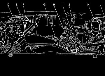
Four-Wheel Drive If your vehicle has four-wheel drive, you will see the buttons shown below. You can send your engine’s driving power to all four wheels for extra traction. To get the most satisfaction out of four-wheel drive, you must be familiar with its operation. Read the part that follows before using four-wheel drive. Notice: Driving on clean, dry pavement in Four-Wheel-Drive High or Four-Wheel-Drive Low for an extended period of time may cause premature wear on your vehicle’s powertrain. Do not drive on clean, dry pavement in Four-Wheel Drive High or Four-Wheel-Drive Low for extended periods of time.
The transfer case buttons are located to the left of the instrument panel cluster.
2-34
The front axle locks and unlocks automatically when you shift the transfer case. Some delay for the axle to lock or unlock is normal. For information on StabiliTrak®, see StabiliTrak® System on page 4-9. Use these buttons to shift into and out of four-wheel drive. You can choose among four driving settings:
AUTO 4WD (Automatic Four-Wheel Drive): This setting is ideal for use when road surface traction conditions are variable. When driving your vehicle in AUTO 4WD, the front axle is engaged, but the vehicle’s power is sent only to the rear wheels. When the vehicle senses a loss of traction, the system will automatically engage four-wheel drive. Driving in this mode results in slightly lower fuel economy than Two-Wheel High. 2 m (Two-Wheel High): This setting is used for driving in most street and highway situations. Your front axle is not engaged in two-wheel drive. This setting also provides the best fuel economy. 4 m (Four-Wheel High): Use the four-wheel high position when you need extra traction, such as on snowy or icy roads or in most off-road situations. This setting also engages your front axle to help drive your vehicle. This is the best setting to use when plowing snow.
4 n (Four-Wheel Low): This setting also engages your front axle and delivers extra torque. You may never need this setting. It sends maximum power to all four wheels. You might choose Four Wheel-Low if you are driving off-road in deep sand, deep mud, deep snow, and while climbing or descending steep hills. StabiliTrak® will not engage in this mode. See StabiliTrak® System on page 4-9 for more information.
{CAUTION:
Shifting the transfer case to NEUTRAL can cause your vehicle to roll even if the transmission is in PARK (P). You or someone else could be seriously injured. Be sure to set the parking brake before placing the transfer case in NEUTRAL. See Parking Brake on page 2-38.
NEUTRAL (N): Shift the vehicle’s transfer case to NEUTRAL only when towing your vehicle. See Recreational Vehicle Towing on page 4-57 or Towing Your Vehicle on page 4-57 for more information.
Indicator lights in the button show which setting you are in. The indicator lights will come on briefly when you turn on the ignition and one will stay on. If the lights do not come on, you should take your vehicle to your dealer for service. An indicator light will flash while shifting the transfer case. It will remain illuminated when the shift is complete. If for some reason the transfer case cannot make a requested shift, it will return to the last chosen setting. If the SERVICE 4WD message stays on, you should take your vehicle to your dealer for service. See “Service 4WD message” under DIC Warnings and Messages on page 3-50. Shifting Into Four-Wheel High or AUTO 4WD (Automatic Four-Wheel Drive) Press and release the Four-Wheel High or AUTO 4WD button. This can be done at any speed, except when shifting from Four-Wheel Low, and the indicator light will flash while shifting. It will remain on when the shift is completed. Shifting Into Two-Wheel High Press and release the Two-Wheel High button. This can be done at any speed, except when shifting from Four-Wheel Low.
2-35
Shifting Out of Four-Wheel Low To shift from Four-Wheel Low to Four-Wheel High, AUTO 4WD or Two-Wheel High, your vehicle must be stopped or moving less than 3 mph (5 km/h) with the transmission in NEUTRAL (N) and the ignition in RUN. The preferred method for shifting out of Four-Wheel Low is to have your vehicle moving 1 to 2 mph (1.6 to 3.2 km/h). Press and release the Four-Wheel High, AUTO 4WD or Two-Wheel High button. You must wait for the Four-Wheel High, AUTO 4WD or Two-Wheel High indicator light to stop flashing and remain on before shifting your transmission into gear. Notice: Shifting the transmission into gear before the Four-Wheel Low indicator light has stopped flashing could damage the transfer case. To help avoid damaging your vehicle, always wait for the Four-Wheel Low indicator light to stop flashing before shifting the transmission into gear. It is typical for your vehicle to exhibit significant engagement noise and bump when shifting between Four-Wheel Low and Four-Wheel High ranges or from NEUTRAL with the engine running.
Shifting Into Four-Wheel Low To shift to the Four-Wheel Low position, the ignition must be in RUN and the vehicle must be stopped or moving less than 3 mph (5 km/h) with the transmission in NEUTRAL (N). The preferred method for shifting into four-wheel low is to have your vehicle moving 1 to 2 mph (1.6 to 3.2 km/h). Press and release the Four-Wheel Low button. You must wait for the four-wheel low indicator light to stop flashing and remain on before shifting your transmission in gear. Notice: Shifting the transmission into gear before the Four-Wheel Low indicator light has stopped flashing could damage the transfer case. To help avoid damaging your vehicle, always wait for the Four-Wheel Low indicator light to stop flashing before shifting the transmission into gear. It is typical for your vehicle to exhibit significant engagement noise and bump when shifting between Four-Wheel Low and Four-Wheel High ranges or from NEUTRAL with the engine running. If the Four-Wheel Low button is pressed when your vehicle is in gear and/or moving, the Four-Wheel Low indicator light will flash for 30 seconds and not complete the shift unless your vehicle is moving less than 3 mph (5 km/h) and the transmission is in NEUTRAL (N). After 30 seconds the transfer case will shift to Four-Wheel High mode.
2-36
If the Four-Wheel High, AUTO 4WD or Two-Wheel High switch is pressed when your vehicle is in gear and/or moving, the Four-Wheel High, AUTO 4WD or Two-Wheel High indicator light will flash for 30 seconds but will not complete the shift unless your vehicle is moving less than 3 mph (5 km/h) and the transmission is in NEUTRAL (N). Shifting into NEUTRAL To shift the transfer case to NEUTRAL do the following:
1. Make sure the vehicle is parked so that it will
not roll.
2. Set the parking brake. See Parking Brake on
page 2-38 for more information.
3. Start the vehicle or turn the ignition to RUN. 4. Put the transmission in NEUTRAL (N). 5. Shift the transfer case to Two-Wheel High. 6. Simultaneously press and hold the Two-Wheel High
and Four-Wheel Low buttons for 10 seconds. The NEUTRAL light will come on when the transfer case shift to NEUTRAL is complete.
7. If the engine is running, verify that the transmission
is in NEUTRAL (N) by shifting the transmission to REVERSE (R) for one second, then shift the transmission to DRIVE (D) for one second.
8. Turn the ignition to ACCESSORY, which will turn
the engine off.
9. Place the transmission shift lever in PARK (P). 10. Turn the ignition to LOCK. Shifting Out of NEUTRAL To shift out of NEUTRAL do the following: 1. Set the parking brake and apply the regular brake
pedal.
2. Shift the transmission to NEUTRAL (N) and turn the
ignition to RUN with the engine off.
3. Press the button for the desired transfer case shift
position (Two-Wheel High, Four-Wheel High, AUTO 4WD, or Four-Wheel Low). After the transfer case has shifted out of NEUTRAL the NEUTRAL light will go out.
2-37
4. Release the parking brake. Notice: Shifting the transmission into gear before the Four-Wheel Low indicator light has stopped flashing could damage the transfer case. To help avoid damaging your vehicle, always wait for the Four-Wheel Low indicator light to stop flashing before shifting the transmission into gear. 5. Start the engine and shift the transmission to the
desired position.
Excessively shifting the transfer case into or out of the different modes may cause the transfer case to enter the shift protection mode. This will protect the transfer case from possible damage and will only allow the transfer case to respond to one shift per 10 seconds. The transfer case may stay in this mode for up to three minutes.
Parking Brake To set the parking brake, hold the regular brake pedal down with your right foot. Push down the parking brake pedal with your left foot. A chime will activate and the warning light will flash when the parking brake is applied and the vehicle is moving at least 3 mph (5 km/h) for at least three seconds.
To release the parking brake, hold the regular brake pedal down. Pull the bottom edge of the lever, located above the parking brake pedal, with the parking brake symbol, to release the parking brake.
2-38
If the ignition is on when the parking brake is released, the brake system warning light will go off. Notice: Driving with the parking brake on can overheat the brake system and cause premature wear or damage to brake system parts. Verify that the parking brake is fully released and the brake warning light is off before driving. If you are towing a trailer and are parking on any hill, see Towing a Trailer on page 4-62.
Shifting Into Park (P)
{CAUTION:
It can be dangerous to get out of your vehicle if the shift lever is not fully in PARK (P) with the parking brake firmly set. Your vehicle can roll. If you have left the engine running, the vehicle can move suddenly. You or others could be injured. To be sure your vehicle will not move, even when you are on fairly level ground, use the steps that follow. With
CAUTION:
(Continued)
CAUTION:
(Continued)
four-wheel drive, if your transfer case is in NEUTRAL, your vehicle will be free to roll, even if your shift lever is in PARK (P). So, be sure the transfer case is in a drive gear — not in NEUTRAL. If you are pulling a trailer, see Towing a Trailer on page 4-62.
1. Hold the brake pedal down with your right foot and
set the parking brake.
2. Move the shift lever into the PARK (P) position by pulling the shift lever toward you and moving it up as far as it will go.
3. Be sure the transfer case is in a drive gear — not
in NEUTRAL (N).
4. Turn the ignition key to LOCK. 5. Remove the key and take it with you. If you can
leave your vehicle with the ignition key in your hand, your vehicle is in PARK (P).
2-39
Leaving Your Vehicle With the Engine Running
{CAUTION:
It can be dangerous to leave your vehicle with the engine running. Your vehicle could move suddenly if the shift lever is not fully in PARK (P) with the parking brake firmly set. If you have four-wheel drive and your transfer case is in NEUTRAL, your vehicle will be free to roll, even if your shift lever is in PARK (P). So be sure the transfer case is in a drive gear — not in NEUTRAL. And, if you leave the vehicle with the engine running, it could overheat and even catch fire. You or others could be injured. Do not leave your vehicle with the engine running unless you have to.
If you have to leave your vehicle with the engine running, be sure your vehicle is in PARK (P) and the parking brake is firmly set before you leave it. After you move the shift lever into PARK (P), hold the regular brake pedal down. Then, see if you can move the shift lever away from PARK (P) without first pulling it toward you. If you can, it means that the shift lever was not fully locked into PARK (P). Torque Lock If you are parking on a hill and you do not shift your transmission into PARK (P) properly, the weight of the vehicle may put too much force on the parking pawl in the transmission. You may find it difficult to pull the shift lever out of PARK (P). This is called “torque lock.” To prevent torque lock, set the parking brake and then shift into PARK (P) properly before you leave the driver’s seat. To find out how, see Shifting Into Park (P) on page 2-39. When you are ready to drive, move the shift lever out of PARK (P) before you release the parking brake. If torque lock does occur, you may need to have another vehicle push yours a little uphill to take some of the pressure from the parking pawl in the transmission, so you can pull the shift lever out of PARK (P).
2-40
Shifting Out of Park (P) Your vehicle has an automatic transmission shift lock control system. You have to fully apply your regular brakes before you can shift from PARK (P) when the ignition is in RUN. See Automatic Transmission Operation on page 2-30. If you cannot shift out of PARK (P), ease pressure on the shift lever and push the shift lever all the way up into PARK (P) as you maintain brake application. Then, move the shift lever into the gear you want. If you ever hold the brake pedal down but still cannot shift out of PARK (P), try this: 1. Turn the key to ACCESSORY. There is no shift
interlock in this key position.
2. Apply and hold the brake until the end of Step 4. 3. Shift the vehicle to NEUTRAL (N). 4. Start the vehicle and then shift to the drive gear
you want.
5. Have the system fixed as soon as possible.
Parking Over Things That Burn
{CAUTION:
Things that can burn could touch hot exhaust parts under your vehicle and ignite. Do not park over papers, leaves, dry grass, or other things that can burn.
2-41
Running the Engine While Parked It is better not to park with the engine running. But if you ever have to, here are some things to know.
{CAUTION:
Idling the engine with the climate control system off could allow dangerous exhaust into your vehicle. See the earlier caution under Engine Exhaust on page 2-42. Also, idling in a closed-in place can let deadly carbon monoxide (CO) into your vehicle even if the climate control fan is at the highest setting. One place this can happen is a garage. Exhaust — with CO — can come in easily. NEVER park in a garage with the engine running. Another closed-in place can be a blizzard. See Winter Driving on page 4-40.
Engine Exhaust
{CAUTION:
Engine exhaust can kill. It contains the gas carbon monoxide (CO), which you cannot see or smell. It can cause unconsciousness and death. You might have exhaust coming in if:
(cid:127) Your exhaust system sounds strange or
different.
(cid:127) Your vehicle gets rusty underneath. (cid:127) Your vehicle was damaged in a collision. (cid:127) Your vehicle was damaged when driving over high points on the road or over road debris.
(cid:127) Repairs were not done correctly. (cid:127) Your vehicle or exhaust system had been
modified improperly.
If you ever suspect exhaust is coming into your vehicle:
(cid:127) Drive it only with all the windows down to
blow out any CO; and
(cid:127) Have your vehicle fixed immediately.
2-42
{CAUTION:
It can be dangerous to get out of your vehicle if the shift lever is not fully in PARK (P) with the parking brake firmly set. Your vehicle can roll. Do not leave your vehicle when the engine is running unless you have to. If you have left the engine running, the vehicle can move suddenly. You or others could be injured. To be sure your vehicle will not move, even when you are on fairly level ground, always set your parking brake and move the shift lever to PARK (P).
{CAUTION:
Four-wheel drive vehicles with the transfer case in NEUTRAL will allow the vehicle to roll, even if your shift lever is in PARK (P). So, be sure the transfer case is in a drive gear — not in NEUTRAL. Always set your parking brake.
Follow the proper steps to be sure your vehicle will not move. See Shifting Into Park (P) on page 2-39. If you are pulling a trailer, see Towing a Trailer on page 4-62. Mirrors Automatic Dimming Rearview Mirror with OnStar® and Compass Your vehicle may have an automatic-dimming rearview mirror with a compass and the OnStar® system. There are three additional buttons for the OnStar® system. See your dealer for more information on the system and how to subscribe to OnStar®. See OnStar® System on page 2-55 for more information about the services OnStar® provides. Mirror Operation When turned on, this mirror automatically dims to the proper level to minimize glare from any headlamps behind you after dark. O(On/Off): This is the on/off button for the automatic dimming feature and compass. Press the far left button, located below the mirror face, for up to three seconds to turn the feature on and off. A light on the mirror will be lit while the feature is turned on.
2-43
Compass Operation Press the on/off button once to turn the compass on or off. There is a compass display in the window in the upper right corner of the mirror face. The compass displays a maximum of two characters. For example, “NE” is displayed for north-east. Compass Calibration Press and hold the on/off button down for nine seconds to activate the compass calibration mode. CAL will be displayed in the compass window on the mirror. The compass can be calibrated by driving the vehicle in circles at 5 mph (8 km/h) or less until the display reads a direction.
Compass Variance Compass variance is the difference between earth’s magnetic north and true geographic north. The mirror is set to zone eight upon leaving the factory. It will be necessary to adjust the compass to compensate for compass variance if you live outside zone eight. Under certain circumstances, such as during a long distance cross-country trip, it will be necessary to adjust for compass variance. If not adjusted to account for compass variance, your compass could give false readings. To adjust for compass variance, do the following: 1. Find your current location and variance zone
number on the map.
2-44
Automatic Dimming Rearview Mirror with OnStar®, Compass and Temperature Display Your vehicle may have this feature. When on, the automatic dimming mirror dims to the proper level to minimize glare from lights behind you after dark. The mirror has a dual display in the upper right corner of the mirror face that shows the compass reading and the outside temperature. Control buttons for the OnStar® system are at the bottom of the mirror. See OnStar® System on page 2-55
for more information about the services OnStar® provides. P (On/Off): This is the on/off button.2-45
2. Press and hold the on/off button for six seconds. Release the button when ZONE is displayed. The number shown is the current zone number.
3. Scroll through the zone numbers that appear in the compass/temperature window on the mirror by pressing the on/off button. Once you find your zone number, release the button. After about four seconds, the mirror will return to the compass display, and the new zone number will be set.
Temperature and Compass Display Press the on/off button, located to the far left, briefly to turn the compass/temperature display on or off. If the display reads CAL, the compass needs to be calibrated. For more information, see “Compass Calibration” following. To adjust between Fahrenheit and Celsius, do the following: 1. Press and hold the on/off button for approximately four seconds until either a flashing F or C appears.
2. Press the button again to change the display to the desired unit of measurement. After approximately four seconds of inactivity, the new unit will be locked in and the compass/temperature display will return. If an abnormal temperature reading is displayed for an extended period of time, please see your GM dealer. Under certain circumstances, a delay in updating the temperature is normal.
2-46
Automatic Dimming Mirror Operation The automatic dimming mirror function is turned on automatically each time the ignition is started. To operate the automatic dimming mirror, do the following: 1. Make sure the green indicator light, located to the left
of the on/off button, is lit. If it is not, press and hold the on/off button for approximately six seconds until the green light comes on, indicating that the mirror is in automatic dimming mode.
2. Turn off the automatic dimming mirror function by
pressing and holding the on/off button for approximately six seconds, until the green indicator light turns off.
Compass Variance The mirror is set in zone eight upon leaving the factory. It will be necessary to adjust the compass to compensate for compass variance if the vehicle is outside of zone eight. Under certain circumstances, as during a long distance cross-country trip, it will be necessary to adjust for compass variance. Compass variance is the difference between earth’s magnetic north and true geographic north. If not adjusted to account for compass variance, the compass could give false readings. To adjust for compass variance, do the following: 1. Find your current location and variance zone
number on the following zone map.
Compass Calibration The compass may need calibration if one of the following occurs: (cid:127) After approximately five seconds, the display does
not show a compass heading, N for North, for example, there may be a strong magnetic field interfering with the compass. Such interference may be caused by a magnetic antenna mount, magnetic note pad holder, or a similar magnetic item. The compass does not display the correct heading and the compass zone variance is set correctly.
In order to calibrate, CAL must be displayed in the mirror compass windows. If CAL is not displayed, push the on/off button for approximately 12 seconds or until CAL is displayed. The compass can be calibrated by driving the vehicle in circles at 5 mph (8 km/h) or less until the display reads a direction.
2-47
2. Press and hold the on/off button until a Z and a
zone number appears in the display. The compass is now in zone mode.
3. Keep pressing the on/off button until the desired zone number appears in the display. Release the button. After approximately four seconds of inactivity, the new zone number will be locked in and the compass/temperature display will return.
4. Calibrate the compass as described next.
(cid:127) Passenger Airbag Indicator The vehicle may be equipped with a passenger airbag indicator, on the mirror glass, just above the buttons. For more information, see Passenger Sensing System on page 1-61 and Passenger Airbag Status Indicator on page 3-32. Cleaning the Mirror When cleaning the mirror, use a paper towel or similar material dampened with glass cleaner. Do not spray glass cleaner directly on the mirror as that may cause the liquid cleaner to enter the mirror housing.
Automatic Dimming Rearview Mirror with Compass Your vehicle may have an automatic-dimming rearview mirror with a compass. Mirror Operation When turned on, this mirror automatically dims to the proper level to minimize glare from any headlamps behind you after dark.
O(On/Off): This is the on/off button for the automatic dimming feature and compass. Press the far left button, located below the mirror face, for up to three seconds to turn the feature on and off. A light on the mirror will be lit while the feature is turned on. Compass Operation Press the on/off button once to turn the compass on or off. There is a compass display in the window in the upper right corner of the mirror face. The compass displays a maximum of two characters. For example, “NE” is displayed for north-east. Compass Calibration Press and hold the on/off button down for nine seconds to activate the compass calibration mode. CAL will be displayed in the compass window on the mirror. The compass can be calibrated by driving the vehicle in circles at 5 mph (8 km/h) or less until the display reads a direction.
2-48
Compass Variance Compass variance is the difference between earth’s magnetic north and true geographic north. The mirror is set to zone eight upon leaving the factory. It will be necessary to adjust the compass to compensate for compass variance if you live outside zone eight. Under certain circumstances, such as during a long distance cross-country trip, it will be necessary to adjust for compass variance. If not adjusted to account for compass variance, your compass could give false readings. To adjust for compass variance, do the following: 1. Find your current location and variance zone
number on the map.
2. Press and hold the on/off button for six seconds. Release the button when ZONE is displayed. The number shown is the current zone number.
3. Scroll through the zone numbers that appear in the compass/temperature window on the mirror by pressing the on/off button. Once you find your zone number, release the button. After about four seconds, the mirror will return to the compass display, and the new zone number will be set.
2-49
Automatic Dimming Rearview Mirror with Compass and Temperature Display Your vehicle may be equipped with this feature. When on, an automatic dimming mirror will dim to the proper level to minimize glare from lights behind you after dark. The mirror also includes a dual display in the upper right corner of the mirror with the compass reading and the outside temperature. The display can be turned on or off by briefly pressing either the TEMP or the COMP button. Temperature Display The temperature can be displayed by pressing the TEMP button. Pressing the TEMP button once briefly, will toggle the temperature reading on and off. To alternate the temperature reading between Fahrenheit and Celsius, press and hold the TEMP button for approximately four seconds until the display blinks F and C. Press and release the TEMP button to toggle between the Fahrenheit and Celsius readings. After approximately four seconds of inactivity, the display will stop blinking and display the last selection made. Press and release the TEMP button to toggle the temperature display between Fahrenheit or Celsius. If an abnormal reading is displayed, please consult your GM dealer.
2-50
Automatic Dimming Mirror Operation Press and hold the TEMP button for approximately eight seconds to turn the automatic dimming feature on or off. The indicator light to the left of the TEMP button will turn on or off to indicate when the feature is on. Once the mirror is turned off, it will remain off until it is turned back on, or until the vehicle is restarted. Compass Operation Press the COMP button once briefly to turn the compass on or off. When the ignition is started and the compass feature is on, the compass will show two character boxes for approximately two seconds. After two seconds, the mirror will display the compass heading. Compass Calibration The compass may need calibration if one of the following occurs:
If CAL is displayed while driving in the vehicle.
(cid:127) After approximately five seconds, the display does
not show a compass heading, N for North, for example, there may be a strong magnetic field interfering with the compass. Such interference may be caused by a magnetic antenna mount, magnetic note pad holder, or a similar magnetic item. The compass does not display the correct heading and the compass zone variance is set correctly.
(cid:127) (cid:127) In order to calibrate, CAL must be displayed in the mirror compass windows. If CAL is not displayed, push in the COMP button for approximately eight seconds or until CAL is displayed. The compass can be calibrated by driving the vehicle in circles at 5 mph (8 km/h) or less until the display reads a direction. Compass Variance The mirror is set in zone eight upon leaving the factory. It will be necessary to adjust the compass to compensate for compass variance if the vehicle is outside zone eight. Under certain circumstances, as during a long distance cross-country trip, it will be necessary to adjust for compass variance. Compass variance is the difference between earth’s magnetic north and true geographic north. If not adjusted to account for compass variance, your compass could give false readings. To adjust for compass variance: 1. Find your current location and variance zone
number on the following zone map.
2. Press and hold the COMP button for five seconds
until a zone number appears in the display.
3. Press the COMP button on the bottom of the mirror
until the new zone number appears in the display. After you stop pressing the button, the display will show a compass direction within a few seconds.
2-51
Passenger Airbag Indicator The mirror may be equipped with a passenger airbag indicator on the mirror glass, just above the buttons. If the vehicle has this feature, the mirror will display the word ON, or an airbag symbol in Canada, when the passenger airbag is enabled. See Passenger Sensing System on page 1-61 for more information. Cleaning the Mirror Use a paper towel or similar material dampened with glass cleaner. Do not spray glass cleaner directly on the mirror as that may cause the liquid cleaner to enter the mirror housing.
Outside Camper-Type Mirrors
If your vehicle is equipped with this trailer towing type mirror, they can be adjusted so you can have a clear view of the objects behind you. Pull out the mirror head to extend it for better visibility when towing a trailer. These mirrors can also be manually folded in. On the lower portion of the mirror is a convex mirror. A convex mirror’s surface is curved so you can see more from the driver’s seat.
2-52
Outside Power Mirrors
The controls are located on the driver’s door armrest.
Move the upper selector switch to the left or right to choose the mirror to be adjusted, then press the dots, located below the selector switch on the four-way control pad, to adjust the direction of each mirror. The mirrors may also include a memory function which works in conjunction with the memory seats. See Memory Seat on page 2-90 for more information.
Power Folding Mirrors To fold or unfold the mirrors, move the selector switch, located above the mirror control, to the middle position. The mirror control will illuminate. Press the right or left side of the mirror control to fold or unfold the mirrors. The mirror will adjust as it folds in and will reposition itself once it is unfolded. If the mirrors are accidentally folded/unfolded manually, they may shake or flutter at normal driving speeds and may not stay in the unfolded position. If this happens, the mirrors need to be reset. See “Resetting the Power Folding Mirrors” next. Resetting the Power Folding Mirrors The power folding mirrors will need to be reset if: They are accidently manually folded/unfolded. The mirrors will not stay in the unfolded position. The mirrors shake and flutter at normal driving speeds.
To reset the power folding mirrors, fold and unfold them at least three times using the mirror controls. This will reset them to their normal detent position.
2-53
(cid:127) (cid:127) (cid:127) Outside Convex Mirror
Outside Heated Mirrors
{CAUTION:
A convex mirror can make things (like other vehicles) look farther away than they really are. If you cut too sharply into the right lane, you could hit a vehicle on your right. Check your inside mirror or glance over your shoulder before changing lanes.
The passenger’s side mirror is convex. A convex mirror’s surface is curved so more can be seen from the driver’s seat. It makes things in the mirror appear farther away than they really are.
If the vehicle has heated mirrors, the button to turn this function on or off is located on the climate control panel.
Press this button to warm the driver’s and passenger’s outside rearview mirrors to help clear them of ice, snow, and condensation. If the vehicle has a rear window defogger, the heated mirrors will come on when this button is pressed. See “Rear Window Defogger” under Dual Automatic Climate Control System on page 3-22 for more information.
2-54
Outside Automatic Dimming Mirror with Curb View Assist Your vehicle may have this feature. The driver’s outside mirror will adjust for the glare of the headlamps behind you. See Automatic Dimming Rearview Mirror with OnStar®, Compass and Temperature Display on page 2-45. Your vehicle’s mirrors will also be capable of performing the curb view assist mirror function. This feature will cause the passenger’s and/or driver’s mirror to tilt to a preselected position when the vehicle is in REVERSE (R). This feature may be useful in allowing you to view the curb when you are parallel parking. When the vehicle is shifted out of REVERSE (R) and a short delay has occurred, the passenger’s and/or driver’s mirror will return to its original position. To change the preselected tilt position, adjust the mirrors to the desired position while the vehicle is in REVERSE (R). When the vehicle is shifted out of REVERSE (R), this new position is saved in memory as the tilt position. This feature can be enabled/disabled through the Driver Information Center. See DIC Vehicle Customization on page 3-60 for more information.
OnStar® System
OnStar® uses global positioning system (GPS) satellite technology, wireless communications, and live advisors to provide you with a wide range of safety, security, information, and convenience services. If your airbags deploy, the system is designed to make an automatic call to OnStar® Emergency where we can request emergency services be sent to your location. If you lock your keys in the car, call OnStar® at 1-888-4-ONSTAR and they can send a signal to unlock your doors. if you need roadside assistance, press the OnStar® button and they will get you the help you need.
2-55
A complete OnStar® User’s Guide and the Terms and Conditions of the OnStar® Subscription Service Agreement are included in the vehicle’s glove box literature. For more information, visit www.onstar.com or www.onstar.ca. Contact OnStar® at 1-888-4-ONSTAR (1-888-466-7827), or press the OnStar® button to speak to an OnStar® advisor 24 hours a day, 7 days a week. Terms and conditions of the Subscription Service Agreement can be found at www.onstar.com or www.onstar.ca. OnStar® Services For new vehicles equipped with OnStar®, the Safe and Sound plan is included for one year from the date of purchase. The OnStar® subscription can be extended beyond the first year, or upgraded to the Directions and Connections® Plan to meet your needs. For more information, press the OnStar® button to speak with an advisor.
Safe and Sound Plan (cid:127) Automatic Notification of Airbag Deployment (cid:127) Emergency Services (cid:127) Roadside Assistance (cid:127) Stolen Vehicle Tracking (cid:127) AccidentAssist (cid:127) Remote Door Unlock/Vehicle Alert (cid:127) Remote Diagnostics (cid:127) Online Concierge Directions and Connections® Plan (cid:127) All Safe and Sound Plan Services (cid:127) Driving Directions (cid:127) RideAssist
Information and Convenience Services
2-56
(cid:127) OnStar® Personal Calling As an OnStar® subscriber, the Personal Calling capability allows you to make hands-free calls using a wireless system that is integrated into the vehicle. Calls can be placed nationwide using simple voice commands with no additional contracts and no additional roaming charges. To find out more about OnStar® Personal Calling, refer to the OnStar® User’s Guide in the vehicle’s glove box, visit www.onstar.com or www.onstar.ca, or speak to an OnStar® advisor by pressing the OnStar® button or calling 1-888-4-ONSTAR (1-888-466-7827). OnStar® Virtual Advisor Your vehicle may have Virtual Advisor. It is a feature of OnStar® Personal Calling that uses your minutes to access weather, local traffic reports and stock quotes. By pressing the phone button and giving a few simple voice commands, you can browse through the various topics. Customize your information profile at www.myonstar.com. See the OnStar® user’s guide for more information.
OnStar® Steering Wheel Controls
Your vehicle may be equipped with a Talk/Mute button that can be used to interact with OnStar®. See Audio Steering Wheel Controls on page 3-106
for more information.When calling into voice mail systems or to dial directory numbers, press this button once, wait for the response, say the number(s) to be dialed, wait for the number(s) to be repeated and then say “dial.” See the OnStar® user’s guide for more information.
2-57
If your vehicle is equipped with the Universal Home Remote Transmitter, it complies with Part 15 of the FCC Rules. Operation is subject to the following two conditions: (1) this device may not cause harmful interference, and (2) this device must accept any interference received, including interference that may cause undesired operation. This device complies with RSS-210 of Industry Canada. Operation is subject to the following two conditions: (1) this device may not cause interference, and (2) this device must accept any interference received, including interference that may cause undesired operation of the device. Changes and modifications to this system by other than an authorized service facility could void authorization to use this equipment.
Universal Home Remote System
The Universal Home Remote System, a combined universal transmitter and receiver, provides a way to replace up to three hand-held transmitters used to activate devices such as gate operators, garage door openers, entry door locks, security systems, and home lighting.
2-58
Universal Home Remote System Operation Do not use the Universal Home Remote with any garage door opener that does not have the “stop and reverse” feature. This includes any garage door opener model manufactured before April 1, 1982. If you have a newer garage door opener with rolling codes, please be sure to follow Steps 6 through 8 to complete the programming of your Universal Home Remote Transmitter. Read the instructions completely before attempting to program the Universal Home Remote. Because of the steps involved, it may be helpful to have another person available to assist you in the programming steps. Keep the original hand-held transmitter for use in other vehicles as well as for future Universal Home Remote programming. It is also recommended that upon the sale of the vehicle, the programmed Universal Home Remote buttons should be erased for security purposes. See “Erasing Universal Home Remote Buttons” later in this section or, for assistance, see Customer Assistance Offices on page 7-4.
Be sure that people and objects are clear of the garage door or gate operator you are programming. When programming a garage door, it is advised to park outside of the garage. It is recommended that a new battery be installed in your hand-held transmitter for quicker and more accurate transmission of the radio-frequency signal. Programming Universal Home Remote Follow these steps to program up to three channels: 1. Press and hold down the two outside Universal Home Remote buttons, releasing only when the Universal Home Remote indicator light begins to flash, after 20 seconds. Do not hold down the buttons for longer than 30 seconds and do not repeat this step to program a second and/or third hand-held transmitter to the remaining two Universal Home Remote buttons.
2. Position the end of your hand-held transmitter about 1 to 3 inches (3 to 8 cm) away from the Universal Home Remote buttons while keeping the indicator light in view.
2-59
3. Simultaneously press and hold both the desired
Universal Home Remote button and the hand-held transmitter button. Do not release the buttons until Step 4 has been completed. Some entry gates and garage door openers may require you to substitute Step 3 with the procedure noted in “Gate Operator and Canadian Programming” later in this section.
4. The indicator light will flash slowly at first and then rapidly after Universal Home Remote successfully receives the frequency signal from the hand-held transmitter. Release both buttons.
5. Press and hold the newly-trained Universal Home
Remote button and observe the indicator light. If the indicator light stays on constantly, programming is complete and your device should activate when the Universal Home Remote button is pressed and released. To program the remaining two Universal Home Remote buttons, begin with Step 2 under “Programming Universal Home Remote.” Do not repeat Step 1 as this will erase all of the programmed channels. If the indicator light blinks rapidly for two seconds and then turns to a constant light, continue with Steps 6 through 8 following to complete the programming of a rolling-code equipped device, most commonly, a garage door opener.
2-60
6. Locate in the garage, the garage door opener receiver (motor-head unit). Locate the “Learn” or “Smart” button. This can usually be found where the hanging antenna wire is attached to the motor-head unit.
7. Firmly press and release the “Learn” or “Smart”
button. The name and color of the button may vary by manufacturer. You will have 30 seconds to start Step 8.
8. Return to the vehicle. Firmly press and hold the programmed Universal Home Remote button for two seconds, then release. Repeat the press/hold/release sequence a second time, and depending on the brand of the garage door opener, or other rolling code device, repeat this sequence a third time to complete the programming. The Universal Home Remote should now activate your rolling-code equipped device.
To program the remaining two Universal Home Remote buttons, begin with Step 2 of “Programming Universal Home Remote.” You do not want to repeat Step 1, as this will erase all previous programming from the Universal Home Remote buttons.
Gate Operator and Canadian Programming Canadian radio-frequency laws require transmitter signals to time out or quit after several seconds of transmission. This may not be long enough for Universal Home Remote to pick up the signal during programming. Similarly, some U.S. gate operators are manufactured to time out in the same manner. If you live in Canada, or you are having difficulty programming a gate operator or garage door opener by using the “Programming Universal Home Remote” procedures, regardless of where you live, replace Step 3 under “Programming Universal Home Remote” with the following: Continue to press and hold the Universal Home Remote button while you press and release every two seconds (cycle) the hand-held transmitter button until the frequency signal has been successfully accepted by the Universal Home Remote. The Universal Home Remote indicator light will flash slowly at first and then rapidly. Proceed with Step 4 under “Programming Universal Home Remote” to complete.
Using Universal Home Remote Press and hold the appropriate Universal Home Remote button for at least half of a second. The indicator light will come on while the signal is being transmitted. Erasing Universal Home Remote Buttons To erase programming from the three Universal Home Remote buttons do the following: 1. Press and hold down the two outside buttons until the indicator light begins to flash, after 20 seconds. Do not hold the two outside buttons for longer than 30 seconds.
2. Release both buttons. The Universal Home Remote is now in the train (learning) mode and can be programmed at any time beginning with Step 2 under “Programming Universal Home Remote” shown earlier in this section. Individual buttons cannot be erased, but they can be reprogrammed. See “Reprogramming a Single Universal Home Remote Button” following this section.
2-61
Cupholder(s) Your vehicle may be equipped with cupholders for the front and rear passengers. The cupholders are located in the center console for the front passengers and on the rear of the center console for the rear passengers. To use the front cupholders, press down on the access door and release. The door will then open. Push the door back down to close it. To use the rear cupholders, pull down on the door located on the back of the console. The front cupholder may be removed for cleaning by pushing down and then back on the cupholder.
Center Overhead Console Your vehicle may have an overhead console equipped with reading lights and a small storage area. Press the button next to the light to turn it on. Press it again to turn it off.
Reprogramming a Single Universal Home Remote Button To program a device to Universal Home Remote using a Universal Home Remote button previously trained, follow these steps: 1. Press and hold the desired Universal Home
Remote button. Do not release the button. 2. The indicator light will begin to flash after
20 seconds. While still holding the Universal Home Remote button, proceed with Step 2 under “Programming Universal Home Remote” shown earlier in this section.
For additional information on Universal Home Remote, see Customer Assistance Offices on page 7-4. Storage Areas
Glove Box Open the glove box by pulling the bottom of the handle upward.
2-62
Front Armrest Storage Area Your vehicle may have a center armrest storage compartment in the front bench seat. To open it, fold down the armrest and press the latch handle located at the front of the armrest. Then, let the lid pop up and swing open.
Center Console Storage Area Your vehicle may have a console compartment with cupholders between the bucket seats. To open it, press the button and swing the console lid open. The rear of the console has a cupholder that swings down for the rear seat passenger to use.
Luggage Carrier You can load things on top of your vehicle if it has this feature. The luggage carrier has slats and siderails attached to the roof and may have crossrails which can be moved back and forth to help secure cargo. Tie the load to the siderails or siderail supports.
Notice: Loading cargo on the luggage carrier that weighs more than 200 lbs (91 kg) or hangs over the rear or sides of the vehicle may damage your vehicle. Load cargo so that it rests on the slats as far forward as possible and against the side rails, making sure to fasten it securely. Don’t exceed the maximum vehicle capacity when loading your vehicle. For more information on vehicle capacity and loading, see Loading Your Vehicle on page 4-46. To prevent damage or loss of cargo as you’re leaving, check now and then to make sure the luggage and cargo are still securely fastened. Be sure the cargo is properly loaded.
If small heavy objects are placed on the roof cut a piece of 3/8 inch plywood to fit inside the crossrails and siderails to spread the load. If plywood is used, tie it to the siderail supports. Tie the load to the crossrails or the siderail supports. Use the crossrails only to keep the load from sliding. To move the crossrails, pull out on the latch release handle at each end. Slide the crossrail to the desired position balancing the force side to side. Push the release handle back into the latched position and slide the crossrail back and forth slightly to be sure the latch snaps securely into place.
2-63
(cid:127) (cid:127) If you need to carry long items, move the crossrails as far apart as they will go. Tie the load to the crossrails and the siderails or siderail supports. Also tie the load to the bumpers. Do not tie the load so tightly that the crossrails or siderails are damaged.
(cid:127) After moving a crossrail, be sure it is securely
locked into the siderail.
Your vehicle has a Center High-Mounted Stoplamp (CHMSL) located above the rear glass. If items are loaded on the roof of the vehicle, care should be taken not to block or damage the CHMSL unit.
Rear Storage Area Your vehicle is equipped with a rear armrest/cupholder for the rear seat passengers. To open it, pull up and then out on the tab, located at the top center of the armrest, and pull the armrest down.
Cargo Cover Panels
{CAUTION:
Improperly stored cargo cover panels could be thrown about the vehicle during a collision or sudden maneuver. You or others could be injured. If you remove a panel, always store it in the proper storage location. When you put it back, always be sure that is securely reattached.
Notice: Exceeding the weight limit of 250 lbs (113 kg) can damage the cargo covers, and the repairs would not be covered by your warranty. Do not put anything on top of the cargo covers over the weight limit. Your vehicle may be equipped with a three-piece cargo cover system. The cargo panels can be removed and stored in the cargo area of the vehicle with the cargo panel storage bag.
2-64
(cid:127) To remove a cargo panel(s), do the following: 1. Lower the tailgate. Use the ignition/door key to
unlock the tailgate if it is locked. See Tailgate on page 2-20 for more information on the tailgate.
The panels are embossed on the upper center portion with the numbers 1, 2 and 3. There are also numbered labels on the bottom of the panels. The numbers on the top and bottom of the panels will be used as reference when removing, storing and reinstalling the panels.
2. Remove cargo panel 3 by pulling the left and right cargo panel latches, located on the bottom of each cargo panel, forward to unlock the cargo panel latches.
2-65
3. Pull each cargo panel up and then out from the
side rails and set it aside. Remove as many cargo panels as needed.
4. If cargo panel 1 needs to be removed. There are
latches on both sides that need to be released.
After you have removed each cargo panel, store them within the cargo storage area using the cargo panel storage system.
2-66
Cargo Panel Storage System The three cargo panels can be stored in the cargo area using the storage strap system. To store the panels, do the following:
1. Secure the storage strap system in the cargo storage area by attaching the six clips included on the cargo strap system to the tie down locations on either side of the storage area.
Always use the storage strap system to store the cargo panels during driving. Before storing the cargo panels, be sure that the latches are in the locked position. The latches are in the locked position when they are parallel to the front and back edge of the panel.
2-67
Use the following instructions for the proper storage sequence and location for each panel:
A. Secure the first secondary strap. B. Secure the last secondary strap. C. Put the rest of the strap system towards the top of the lid and tray.
2. Starting with cargo panel 1, load the cargo panel
with latches up and facing away from you.
2-68
3. Store cargo panel 2 by loading the cargo panel with
latches down and facing toward you.
4. Store cargo panel 3 by loading the cargo panel with
latches up and facing away from you.
2-69
5. Move the rest of the strap system inside the cargo
box, covering the three cargo covers (A). Fasten the four strap clips (B).
6. Tighten all straps by pulling on the free end of each
strap.
2-70
7. Close both cross locks at the center of the strap
system to secure tightly.
Panels 3, 2, 1 Loaded
2-71
Reinstalling the Cargo Cover Panels To reinstall a cargo panel do the following. 1. Remove the cargo panel(s) from the storage strap
system. You can either leave the strap system attached to the side of the cargo area while it is not in use, or you can store it inside the top box compartment. See Top-Box Storage on page 2-82 for more information.
2. Starting with cargo panel 1, place the latches in the unlocked position. Place cargo panel 1 on the cargo area rails while holding the back of the cargo panel up.
2-72
Left Side Shown, Right Side Similar
Push the panel forward until it is snug against the midgate and then let the back of the panel down being sure that the pegs align with the receivers.
4. Install cargo cover 2 next. Place the latches in the unlocked position. Place the cargo cover panel on the cargo area rails while holding the back of the cargo panel up.
3. Push both left latches away from you to lock the latches. Remember that there are two latches on each side for panel 1. You should hear a click when each latch locks. Lock the remaining two right latches on panel 1. For any cargo cover panel you must lock the left latch in place before you can lock the right latch. If you do not follow this exactly, the cargo cover panels may not lock in place correctly.
Left Side Shown, Right Side Similar
Push the panel forward until it is snug against the other panel and then let the back of the panel down being sure that the pegs align with the receivers.
2-73
Left Side Shown, Right Side Similar
Push the panel forward until it is snug against the other panel and then let the back of the panel down being sure that the pegs align with the receivers.
5. Push the latches away from you, starting with the
left latch, to lock the panel in place. You should hear a click when each latch locks correctly.
6. Install cargo cover 3 next. Place the latches in the unlocked position. Place the cargo cover panel on the cargo area rails while holding the back of the cargo panel up.
2-74
Folding and Storage of Straps To store the folding straps do the following:
7. Push the latches away from you, starting with the
left latch, to lock the panel in place. You should hear a click when each latch locks.
1. Extend the six strap ends on a flat surface.
2-75
2. Fold the four strap ends towards the center as
shown.
4. Take the long strap and wrap it around the package
Finally, attach the hooks to the webbing.
3. Take the short strap and surround the folded
webbing, forming a package.
2-76
Cargo Tie Downs
Cargo tie downs are located in the rear cargo area that can be used to secure cargo. The tie downs can also be used to secure the cargo cover panel strap system or the tonneau cover storage bag, if equipped. For more information see “Cargo Cover Panels” earlier in this section and Tonneau Cover on page 2-83.
All-Weather Cargo Area Your vehicle can be driven with the cargo panels on or off, the midgate up or down, or with the rear glass in or out. The vehicle has features to help resist the elements and protect cargo inside the cargo area. Parts of the water management system, which is designed to quickly direct water out of the cargo box, include the top drain grates, side rail channels, catch cups, midgate drain, cargo area floor drains and the rubber cargo mat. Even when the water management system is working properly and the vehicle’s cargo cover system is on, water could still accumulate in areas of the vehicle during heavy rains and after going through an automated car wash.
2-77
The areas where water could collect are:
E. Water drainage area around both sides of the box
and the tailgate side
F. Rear drains G. Cargo floor H. Cargo mat Maintenance and Cleaning To ensure that the water management system performs properly, be sure that the midgate, tailgate, and cover system are fully closed and that each part of the water management system is clean and not blocked with debris. Follow the instruction given next in this section for the proper procedures on cleaning each part of the water management system.
A. Top drain grates B. Removable front drain grate (Midgate drain gate) C. Side rail channels and catch cups D. Front drains
2-78
Top Drain Grates – Removal and Cleaning
To remove each drain grate, do the following: 1. Remove the cargo panels or tonneau cover. See
Cargo Cover Panels on page 2-64 or Tonneau Cover on page 2-83 for more information.
The top drain grates are located near the rear glass on both sides of the vehicle. You may need to clean the grates and drains if there seems to be a blockage.
2. Grasp the edges of the grate and pull it out from
the vehicle. Flush the drain with clean water.
2-79
To replace the drain grate do the following:
Side Rail Channels
The side rail channels are located on top of both sides of the cargo area. Flush them out with clean water debris collects inside of them. When loading cargo into the cargo area, be careful not to damage the rails.
1. Line up the clips on the vehicle with the slots in the
grate.
2. When you are sure that the clips are aligned with
the slots, push the grate down firmly.
The grate should clip into place. Do not force the grate if it will not clip into place; realign the clips with the holes and try again.
2-80
Midgate Drain Grate Removal and Cleaning
After hauling dirt, wood chips, pebbles etc. you will need to flush the midgate drain with water. But first you will have to remove the drain grate by using the following steps:
The midgate drain grate is located near the base of the midgate in the cargo area. You will find a removable drain grate covering the drain.
1. Lower the midgate. See Midgate® on page 2-11 for
more information.
2. Pull up on the rear side of the drain grate. 3. Tilt the drain grate away from you and pull it
straight out.
Reverse the procedure to reinstall the drain grate.
2-81
Cargo Area Floor Drains
Top-Box Storage
Your vehicle also has four cargo-area floor drains located under the cargo mat near the sides of the cargo area. These drains should be cleaned periodically to allow water to drain from the cargo area. The cargo mat has cutouts for the drains. Flush the drains through the cutouts. If the cargo area is extremely dirty lift up the edges of the cargo floor mat or take the whole mat out and flush the drains with water.
Your vehicle is equipped with top-box storage units on both side of the vehicle. The passenger side top box contains the tools you will need to change a flat tire. Use the ignition/door key to unlock/lock it. Press the key cylinder button and swing the lid open. Turn on the cargo lamps, if equipped, if you need more light inside. See Exterior Cargo Lamps on page 3-17 for more information.
2-82
Your vehicle may be equipped with a tonneau cover. The main components of the tonneau cover are the following:
Tonneau Cover
{CAUTION:
Improperly stored tonneau cover components could be thrown about the vehicle during a collision or sudden maneuver. You or others could be injured. If you remove the cover, bows and rails, always store them properly in the cargo area. When you put them back, always be sure that they are securely reattached.
A. Front Rail B. Bows C. Side Rails
D. Rear Rail E. Plastic Lip F. Loop
2-83
Removing the Tonneau Cover
1. Starting at the rear corner of the driver’s side of the
vehicle, pull the loop (F) toward you and then pull up so the plastic lip (E) releases from the channel in the rear rail (D) and the side rail (C).
2. Pull the back of the cover out from the rear rail (D).
2-84
3. Roll the cover toward the front of the vehicle. The plastic lip (E) will release from the siderails (C) as you roll the cover forward.
4. Stow the cover using the buckles and the straps
attached to the front rail.
You can also store the tonneau cover outside of the vehicle or use the storage bag included.
2-85
To use the storage bag, do the following:
1. Attach the bag to the cargo tie downs as shown.
Unzip the top of the storage bag.
2. With the tonneau cover rolled up, place it in
the proper compartment in the bag and zip the bag shut.
2-86
Removing the Front/Rear Rails and Bows Before moving on to the next step, you will want to attach the storage bag to the cargo tie downs, if it is not already attached, so you will have a place ready to store the front and back rails and the two bows.
2. Remove the two bows
by gently pushing them against the spring-loaded end. Set the bow aside.
3. With the midgate lowered, enter the rear passenger
compartment of the vehicle. See Midgate® on page 2-11.
1. Remove the rear rail by pulling it straight out from
the side rails. Set the rail aside.
2-87
4. Remove the front rail by first twisting up the edge nearest you, to clear the midgate seals, and then pulling it out from the side rails.
5. Stow both bows and the front and rear rails in the storage bag. When all components of the tonneau cover are secured in the bag properly, zip the bag shut.
Reverse the procedure to reinstall the tonneau cover using the following suggestions: (cid:127) When reinstalling the front rail, start by holding the back edge of the rail up and then twisting the back edge down while pushing it into place.
(cid:127) Both bows are the same size and therefore
interchangeable.
2-88
(cid:127) When placing the bows in the side rails, it is easiest
to place the spring-loaded bow end in first.
Sunroof
(cid:127) When placing the bows, locate the small notches in the side rails. These notches receive the tang on the bow ends and help the bows seat into place.
(cid:127) When reinstalling the tonneau cover, start at the front, near the cab. Place the plastic lip into the front rail, then the rear rail, and finish with the side rails.
To clean the tonneau cover, use mild soap and water. If necessary, use a soft bristle brush to remove dirt trapped in the grain of the material.
Your vehicle may be equipped with a power sliding sunroof. To open or close your sunroof, the ignition needs to be on or Retained Accessory Power (RAP) needs to be active. See Retained Accessory Power (RAP) on page 2-27. Press and release the rear side of the button located in the front overhead console to express-open the glass panel and sunshade. To stop the express-open motion, press the front or rear of the button again. To close the glass panel, press and hold the front of the button. The glass will not be fully seated unless the button is held until the glass stops moving. With the sunroof closed, press the forward side of the button to open the sunroof to the vent position. The sunroof is also equipped with a sunshade which you can pull forward to block sun rays.
2-89
If a hand, arm, or other object is blocking the sunroof glass panel as it is closing, the glass panel will stop at the obstruction. After the obstruction is removed, the glass panel can be closed or opened. Use care not to leave the sunroof open for long periods of time as debris may collect in the tracks. If the battery has been recharged, disconnected or is not working, you may need to reprogram the sunroof. To do this, start the vehicle and press the forward side of the sunroof button until the glass panel moves to a fully closed position. Release, and press again to move to the vent position, which occurs when the sunroof is fully tilted upward and the button is held for an additional twenty seconds. This will reset the memory and enable the sunroof to function properly. Vehicle Personalization In addition to the following features, your vehicle may also have features that can be programmed through the Driver Information Center (DIC). See DIC Vehicle Customization on page 3-60 for more information.
Memory Seat
If your vehicle has this feature, the controls for the memory function are located on the driver’s door.
These buttons are used to program and recall memory settings for the driver’s seat, both the driver’s and passenger’s outside mirrors, and the throttle and brake pedals for vehicles with the adjustable throttle and brake pedal feature. The settings for these features can be saved for up to two drivers.
2-90
To store the memory settings, do the following:
1. While the vehicle is in PARK (P), adjust the driver’s
seat, including the seatback recliner and lumbar, both outside mirrors, and the throttle and brake pedals to your preference.
2. Press and hold the 1 or 2 button of the memory
control for three seconds. A double chime will sound to let you know that the position has been stored.
To repeat the procedure for a second driver, follow the preceding steps, but press the other numbered memory control button. Each time button 1 or 2 is pressed and released while the vehicle is in PARK (P), a single chime will sound and the memory position will be recalled. To stop recall movement of the memory seat feature at any time, press one of the memory buttons or power seat controls. Easy Exit Seat The controls for this memory function are located on the driver’s door. B (Easy Exit Seat): This button is used to program and recall the desired driver’s seat position when exiting or entering the vehicle. The seat position can be saved for up to two drivers.
To store the seat exit position, do the following: 1. Press and release the 1 or 2 button. The seat will
move to the stored memory position.
2. Adjust the seat to the desired exit position. 3. Press and hold the exit button of the memory
control for three seconds. A double chime will sound to let you know that the position has been stored for the selected button 1 or 2.
To repeat the procedure for a second driver, follow the preceding steps, but press the other numbered memory control button. To use the seat exit position, do one of the following: (cid:127) Press the exit button on the memory control.
If this feature is activated in the Driver Information Center (DIC), removing the key from the ignition will move the seat to the exit position.
See “Easy Exit Seat” under DIC Vehicle Customization on page 3-60 for more information on activating this feature in the DIC.
2-91
(cid:127) ✍ NOTES
2-92
Section 3
Instrument Panel
Instrument Panel Overview ...............................3-4
Hazard Warning Flashers ................................3-6
Other Warning Devices ...................................3-6
Horn .............................................................3-6
Tilt Wheel .....................................................3-7
Turn Signal/Multifunction Lever .........................3-7
Turn and Lane-Change Signals ........................3-8
Headlamp High/Low-Beam Changer ..................3-9
Flash-to-Pass .................................................3-9
Windshield Wipers ..........................................3-9
Windshield Washer .......................................3-10
Cruise Control ..............................................3-10
Exterior Lamps .............................................3-14
Headlamps on Reminder ................................3-15
Daytime Running Lamps (DRL) .......................3-15
Automatic Headlamp System ..........................3-15
Fog Lamps ..................................................3-16
Auxiliary Roof Mounted Lamp .........................3-17
Exterior Cargo Lamps ....................................3-17
Instrument Panel Brightness ...........................3-17
Dome Lamps ...............................................3-18
Dome Lamp Override ....................................3-18
Entry/Exit Lighting .........................................3-18
Reading Lamps ............................................3-18Battery Run-Down Protection ..........................3-18
Accessory Power Outlet(s) .............................3-19
Ashtray(s) and Cigarette Lighter ......................3-19
Climate Controls ............................................3-20
Dual Climate Control System ..........................3-20
Dual Automatic Climate Control System ...........3-22
Outlet Adjustment .........................................3-27
Warning Lights, Gages, and Indicators ............3-28
Instrument Panel Cluster ................................3-29
Speedometer and Odometer ...........................3-30
Trip Odometer ..............................................3-30
Tachometer .................................................3-30
Safety Belt Reminder Light .............................3-30
Airbag Readiness Light ..................................3-31
Passenger Airbag Status Indicator ...................3-32
Charging System Light ..................................3-34
Voltmeter Gage ............................................3-34
Brake System Warning Light ..........................3-35
Anti-Lock Brake System Warning Light .............3-36
Low Tire Pressure Warning Light ....................3-37
Traction Off Light ..........................................3-37
Engine Coolant Temperature Gage ..................3-383-1
Section 3
Instrument Panel
Transmission Temperature Gage .....................3-38
Malfunction Indicator Lamp .............................3-40
Oil Pressure Gage ........................................3-42
Security Light ...............................................3-43
Cruise Control Light ......................................3-44
Highbeam On Light .......................................3-44
Tow/Haul Mode Light ....................................3-44
Cargo Lamp Light .........................................3-44
Fuel Gage ...................................................3-45
Low Fuel Warning Light .................................3-45
Driver Information Center (DIC) .......................3-46
DIC Operation and Displays ...........................3-47
DIC Warnings and Messages .........................3-50
DIC Vehicle Customization .............................3-60Audio System(s) .............................................3-66
Setting the Time ...........................................3-67
Radio with CD ..............................................3-68
Radio with Six-Disc CD .................................3-78
Navigation/Radio System ...............................3-93
Rear Seat Entertainment System ....................3-93
Rear Seat Audio (RSA) ................................3-104
Theft-Deterrent Feature ................................3-105
Audio Steering Wheel Controls ......................3-106
Radio Reception .........................................3-107
Care of Your CDs and DVDs ........................3-107
Care of the CD and DVD Player ...................3-108
Fixed Mast Antenna ....................................3-108
XM™ Satellite Radio Antenna System ............3-108
Chime Level Adjustment ...............................3-1083-2
✍ NOTES
3-3
Instrument Panel Overview
3-4
The main components of your instrument panel are the following:
A. Air Outlets. See Outlet Adjustment on page 3-27. B. Exterior Lamps Control. See Exterior Lamps
on page 3-14.
C. Cargo/Top-Box Lamps Button. See Exterior Cargo
Lamps on page 3-17.
D. Automatic Transfer Case Buttons (If Equipped). See
Four-Wheel Drive on page 2-34.
E. OnStar® and Radio Steering Wheel Buttons (If
Equipped). See OnStar® System on page 2-55 and Audio Steering Wheel Controls on page 3-106. F. Instrument Panel Cluster. See Instrument Panel
Cluster on page 3-29.
G. Shift Lever/Tow/Haul Selector Button. See Automatic Transmission Operation on page 2-30 and Tow/Haul Mode on page 2-33.
H. Audio System. See Audio System(s) on page 3-66. I. Dome Override Button. See Dome Lamp Override
on page 3-18.
J. Fog Lamps Button. See Fog Lamps on page 3-16.
K. Turn Signal/Multifunction Lever. See Turn
Signal/Multifunction Lever on page 3-7.
L. Hood Release. See Hood Release on page 5-12. M. Tilt Lever. See Tilt Wheel on page 3-7. N. Driver Information Center (DIC) Buttons. See Driver
Information Center (DIC) on page 3-46.
O. Parking Brake Release. See Parking Brake on
page 2-38.
P. Climate Control System. See Dual Automatic Climate Control System on page 3-22 or Dual Climate Control System on page 3-20.
Q. Lighter (If Equipped) or Accessory Power Outlet (If
Equipped). See Ashtray(s) and Cigarette Lighter on page 3-19 and Accessory Power Outlet(s) on page 3-19.
R. Accessory Power Outlet (If Equipped). See
Accessory Power Outlet(s) on page 3-19.